Do you have a question about the Borg & Overstrom b4 and is the answer not in the manual?
| Brand | Borg & Overstrom |
|---|---|
| Model | b4 |
| Category | Water Dispenser |
| Language | English |
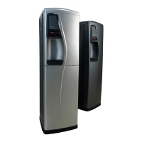
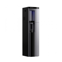
Overview of compact water dispenser types and their availability.
Details on self-contained machines, cabinets, and power supply.
Explanation of how the cold tank is chilled via refrigeration.
How ambient water bypasses the cold tank for dispensing.
Process of chilling and carbonating water for sparkling dispense.
How hot water is heated and dispensed via a tank and solenoid.
Explanation of the instant chilling technology and its benefits.
Diagram and labels of the main parts of the water dispenser.
Details on connecting water and CO2 lines to the unit.
Steps for connecting water supply and initial operation.
Procedures for safely disconnecting and removing the machine.
Table of problems, causes, and suggested actions for no water.
Exploded view of components for the Chilled & Ambient model.
Exploded view of components for the Chilled, Ambient & Hot model.
Exploded view of components for the Chilled, Ambient & Sparkling model.
Exploded view of components for the Chilled, Hot & Sparkling model.
Exploded view of the base cabinet unit for floorstanding models.
Electrical schematic for the Chilled & Ambient configuration.
Electrical schematic for the Chilled, Ambient & Hot configuration.
Electrical schematic for the Chilled, Ambient & Sparkling configuration.
Electrical schematic for the Chilled, Hot & Sparkling configuration.
Diagram showing the water flow for Chilled & Ambient models.
Diagram showing the water flow for Chilled, Ambient & Hot models.
Diagram showing the water flow for Chilled, Ambient & Sparkling models.
Diagram showing the water flow for Chilled, Hot & Sparkling models.
Details on the high-efficiency compression system and refrigerants.
Information on the hot water tank and heating element.
Specified range for chilled water temperature.
Specified maximum temperature for hot water.
Dispensing capacity per hour for different configurations.
Electrical power consumption for various models.
Type of power connection required for the unit.
Specification for connecting the water supply line.
Specification for connecting the CO2 supply line.
Physical dimensions for countertop and base cabinet versions.
Weight specifications for different model configurations.
Information about Borg & Overström as the manufacturer.
Classification of the product.
List of models covered by the declaration.
Directives and regulations the product complies with.
List of specific standards and regulations the product meets.
Formal statement of compliance by the manufacturer.