UPS user manual
Utilizzo dell’UPS
34 OMS02083 REV. A
The string on the second line may have two values, “MASTER” or “SLAVE”. Only one
MASTER UPS can be present in the system; if not there will be a conflict on the data
communication bus.
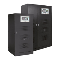
7.1.2 Parallel type
The string on the second line may have two values, “POWER” or “REDUNDANT+x”.
POWER means that the parallel system is so set as to require the presence of all the
UPS units to feed the load.
REDUNDANT+x means that the system is redundant and the redundancy index is
indicated by number “X”. For example, in a system composed of 3 UPS units,
“REDUNDANT+2” means that only one of the UPS units is sufficient to feed the load.
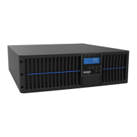
7.1.3 Communication bus monitoring
This menu gives a general indication regarding the communication between the UPS units
composing the system.
The numbers represent the single UPS units.
The letters M and S stand for MASTER and SLAVE respectively.
The highlighted letter indicates that we are working on that specific UPS unit.
A question mark next to a number indicates that that UPS unit is not communicating
on the data bus.
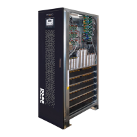
Let us assume to have the following situation:
system composed of 4 UPS units;
UPS2 is currently the MASTER UPS;
we are checking the data communication on UPS3;
UPS4 is not communicating.
The menu will be as shown below.
 Loading...