Installation and start-up of INGENIO PLUS UPS 30÷40 kVA
Installazione e avviamento INGENIO PLUS UPS 30÷40 kVA
82 OMS02082 REV. D
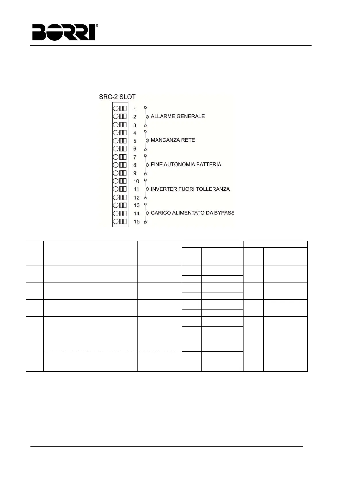
4.7 COLLEGAMENTO SCHEDA RELÈ (OPZIONALE)
L’UPS INGENIO PLUS 30÷40 kVA, nella sua configurazione completa, è provvisto di una
scheda relè per la ripetizione remota di stati di funzionamento e allarmi. Il collegamento elettrico
è realizzato direttamente sui morsetti sul fronte dello slot di interfaccia SRC-2.
Figura 18 – Morsetti scheda relè
Relè Allarmi/Stati Stato
Pin
funzionamento
normale
Nome
funzionamento
normale
RL1 Allarme = A30 ALLARME GENERALE
Non energ. se
allarme presente
2-3 Chiuso
DL1 On
1-2 Aperto
RL2 Allarme = A1 MANCANZA RETE
Non energ. se
allarme presente
5-6 Chiuso
DL2 On
4-5 Aperto
RL3 Allarme = A9 FINE AUT BATTERIA
Non energ. se
allarme presente
8-9 Chiuso
DL3 On
7-8 Aperto
RL4 Allarme = A13 INV FUORI TOL
Non energ. se
allarme presente
11-12
Chiuso
DL4 On
10-11
Aperto
RL5
MODALITA’ NORMALE
Allarme = A16 BYP CARICO
Non energ. se
allarme presente
13-14
14-15
Chiuso
Aperto
DL5 On
MODALITA’ ECO
Stato = S7 BYPASS CARICO
Energizzato se
stato è presente
14-15
13-14
Chiuso
Aperto
Specifica uscita relè:
Tensione 250 Vac Corrente 1A
Tensione 30 Vdc Corrente 1A Carico resistivo