3. Lower head assembly. Lock in place.
4. Loosen bevel lock handle and tilt the head
assembly to 45° bevel. Check the 45° bevel
stop. The bevel indicator should be on the 45°
mark, the 45° bevel stop should be in full contact
with the 45° bevel stop screw, and the blade
should contact the full length of the combination
square (Figure 8).
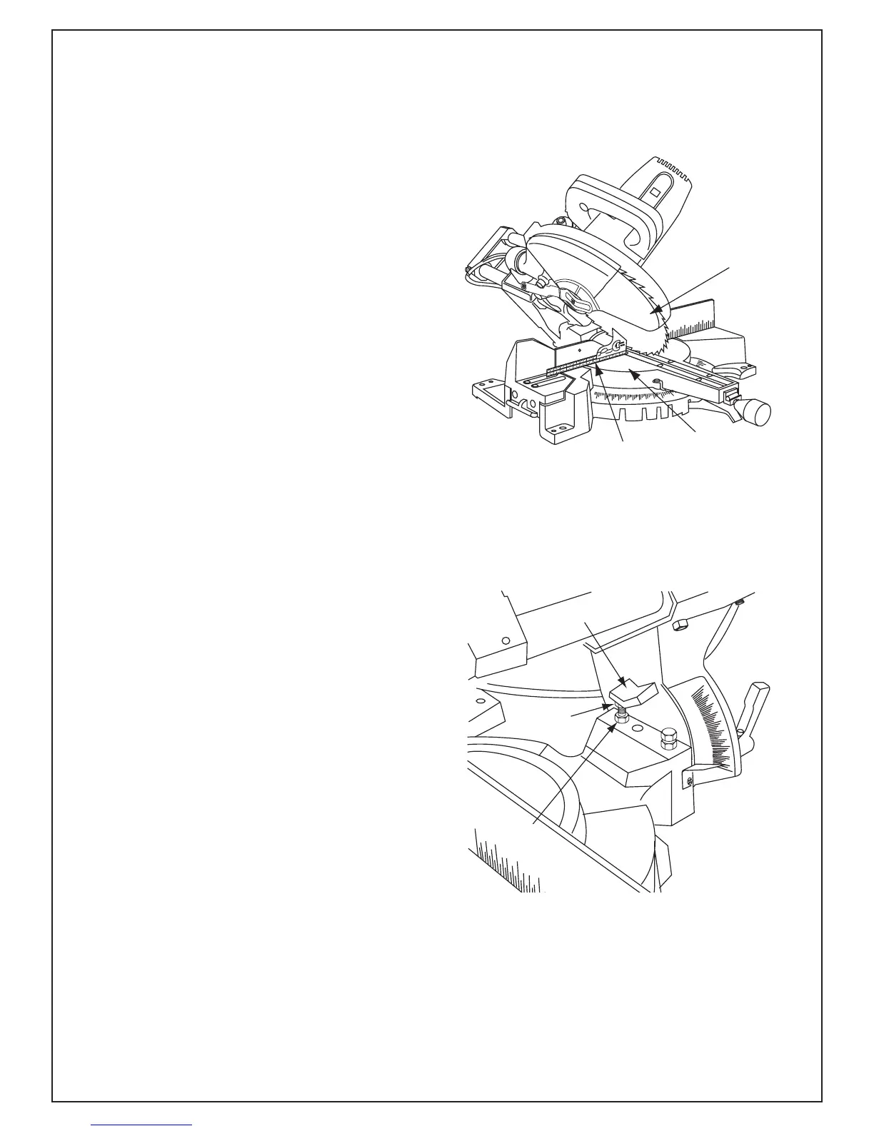
5. If the blade is not 45° with the table, adjust 45°
bevel stop.
45° Blade Alignment
a. Lower the 45° bevel stop screw jam nut
using blade wrench supplied in the handle.
b. Grasp switch handle, move the head
assembly left or right until blade makes con-
tact with the full length of the square.
c. Tighten the bevel lock handle.
d. Adjust 45° bevel stop screw so that the hex
screw head hits the 45° stop at the same
time the blade makes contact with the full
length of the square. Tighten 45° jam nut
(Figure 9).
e. Check that bevel indicator is pointing to the
45° mark on the bevel scale (see Figure 7). If
bevel indicator is not aligned with the 45°
mark, first recheck the blade squareness to
the table and 0° bevel indicator alignment.
Then, repeat the 45° blade alignment and
make appropriate adjustments.
Figure 8. Blade 45° To The Table
Figure 9. Bevel 45° Stop Screw and Jam Nut