8 en | Wiring and Addressing Information Analog detectors and bases
2018.08 | 6.0 | F.01U.123.589 Installation Guide Bosch Security Systems, Inc.
4 Wiring and Addressing Information
4.1 Wiring Information
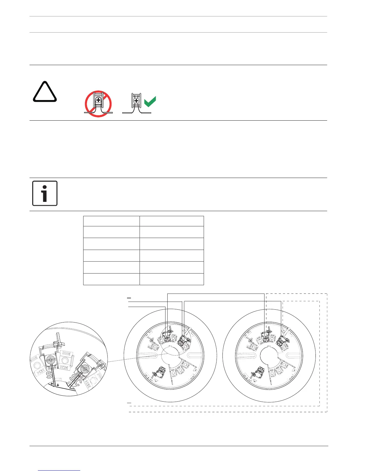
Warning!
Do not twist or loop the wires around the terminals. In and out wires for terminal connection
must be cut, stripped, and inserted as individual ends.
The following wire gauges and maximum line lengths are tested and approved.
– 18 AWG (0.8 mm
2
) -> 4000 ft. (1200m)
– 16 AWG (1.3 mm
2
) -> 6225 ft. (1900m)
– 14 AWG (2.1 mm
2
) -> 7200 ft. (2200m)
– 12 AWG (3.3 mm
2
) -> 9850 ft. (3000m)
Standard non-twisted, non-shielded wiring (plain old wire) for the SLCs is recommended.
Notice!
Voltage drop calculations along with anticipated wire distance should be considered to
ensure a voltage supply of at least 24 V at every detector.
Terminal Lettering Terminal Function
SC SLC bus - IN/OUT
S SLC bus + IN/OUT
S
in
SLC bus + IN
S
out
SLC bus + OUT
C Remote output
 Loading...