Installing the solar pump station | 11
6 720 811 270 (2015/04)AGS10-2, AGS10E-2, AGS20-2, AGS50-2
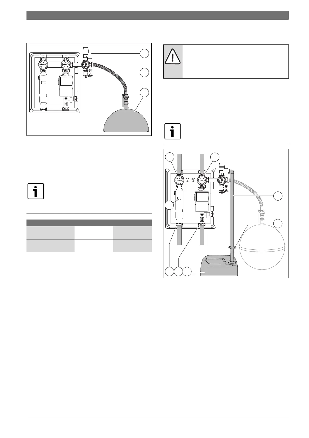
▶ Connect the expansion vessel [3] in the return on the solar pump
station's safety assembly.
Fig. 16
[1] Pressure relief valve
[2] Flexible stainless steel hose from the connection set (available as
accessory)
[3] Expansion vessel
5.5.3 Adjusting the pre-charge pressure of the expansion vessel
To make use of the maximum possible volume:
▶ Set the pre-charge pressure when the vessel is not subjected to load
(i.e. no fluid pressure).
▶ If the calculated pre-charge pressure is higher or lower than the
factory-set pre-charge pressure (see table 7, page 11), correct the
pre-charge pressure accordingly.
5.6 Connecting pipework and pressure relief valve
discharge pipe to the solar pump station
▶ Cut the pipes to length and push them as far as possible into the
compression fitting [1].
▶ Route the discharge pipe [2] from the pressure relief valve so that any
discharge can be seen to empty out into the holding container [4] and
secure it in place with a pipe clip [3].
▶ Maintain an air break.
Fig. 17 Connection to solar pump station
[1] Compression joints on all four outlets
[2] Discharge pipe (not supplied)
[3] Pipe clip (on site)
[4] Empty solar fluid container (holding container)
[5] Connection bracing points
The pre-charge pressure of the expansion vessel is
calculated based on the static system head
1)
plus an
allowance.
▶ Calculate and set pre-charge pressure to at least
1.2 bar.
Flat plate Evacuated tube
Static height
1)
1) A one metre difference in height (between collector array and solar pump station)
equates to 0.1 bar
(10 m) 1.0 bar (10 m) 1.0 bar
+ allowance + 0.4 bar + 1.7 bar
= expansion vessel pre-
charge pressure
= 1.4 bar = 2.7 bar
Table 7 Example: collector-dependent pre-charge pressure
WARNING: Injuries and system damage due to hot heat
transfer medium.
▶ Make sure the discharge pipe size is at least that of the
pressure relief valve (maximum length = 2 m and
maximum of 2 bends).
To tighten the lower compression fittings, you can brace
against the points marked [5] using a 27 mm spanner or
pipe wrench.
7747006489.49-2.ST7747006489.49-2.ST
3
141
1
1
2
5