Installation instructions
15
C 950/C 1050 (Pro TL 175 C/199 C) – 6 720 805 440 (2019/10)
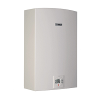
Fig. 7 Side view
For servicing access, a 2ft clearance is recommended to the
front cover.
Table 4 Recommended minimum clearances
4 Installation instructions
4.1 Specialized tools
The following specialized tools may be required for installation:
•Manometer
• Multi-meter
•Combustion Gas Analyzer
4.2 Introduction
Please follow these instructions. Failure to follow
instructions may result in:
▶Damage or injury.
▶Improper operation.
▶ Loss of warranty.
DANGER:
▶ The water heater must be installed by a qualified installer in
accordance with these instructions. If improperly installed,
a hazardous condition such as explosion or carbon
monoxide poisoning could result. Bosch
Thermotechnology Corp. is not responsible for improperly
installed appliances.
Common installation practice is to first determine the venting/
combustion air point of termination, then design the piping
layout back to the heater.
4.3 Venting
DANGER:
▶ Do not reduce the exhaust or combustion air vent pipe
sizes.
▶ Do not common vent with any other vented appliance or
stove.
▶ Do not use Type-B vent as the actual exhaust vent system
for the appliance.
DANGER:
Flue gas poisoning!
▶ Failure to vent the exhaust gases to the outside (see table 5
for proper material) may result in dangerous flue gases
filling the structure in which it is installed.
Greentherm (Pro TL 175/199)
TOP (A) 12”
FRONT (B) 1”
BACK 0”
SIDES 1”
FLOOR (C) 12”