Installation instructions
C 950/C 1050 (Pro TL 175 C/199 C) – 6 720 805 440 (2019/10)
46
▶ Remove the clip and disconnect the drain tube, see fig. 39.
Fig. 39 Disconnect drain tube
▶ Fill the condensate trap by pouring approx.14 oz. (400ml)
of water into the top of the drain tube. To avoid damage to
the appliance use a funnel in this operation, see fig. 40,
page 46.
Fig. 40 Filling the condensate trap after installation
▶ Loosen the three screws of the control unit.
Fig. 41
▶ Put the control unit in service position by engaging its tabs
with the holes in the bottom horizontal sheet metal, see
fig. 42.
▶ Check water level in the condensate trap.
Fig. 42 Water level in condensate trap
▶ After filling reassemble all parts in reverse order.
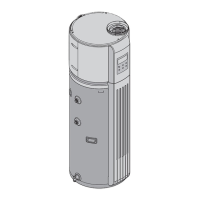
4.12 Domestic hot water recirculation
Although recirculation directly through the tankless water
heater is allowed, temperature stability is improved by
recirculating through a mini-tank as shown in fig. 43. By using
the design in fig. 43, there is no recirculation of hot water
through the tankless water heater and therefore, does not
affect the heat exchanger warranty. Direct recirculation
through the tankless water heater is permissible, however, the
heat exchanger warranty is reduced; contact Bosch
Thermotechnology for further installation requirements. The
following drawing is provided to outline one possible
recirculation design using the water heater in conjunction with
a Bosch electric mini tank water heater. This schematic is for
illustration only and must not be used for actual Installation
without appropriate engineering and technical advice from a
properly licensed professional in the locality where the
installation is made.