Installation instructions
C 950/C 1050 (Pro TL 175 C/199 C) – 6 720 805 440 (2019/10)
26
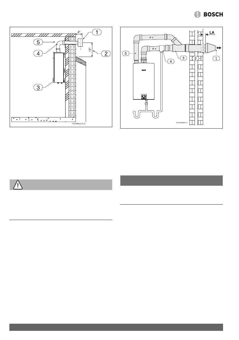
Fig. 14 Horizontal venting installation (combustion air
piping not shown)
[1] Termination
[2] Minimum above ground or normally expected snow
accumulation level
[3] Appliance
[4] Elbow (note: minimum 1ft of straight vent pipe required)
[5] Horizontal run ¼" per foot down to termination
WARNING:
▶ Single pipe penetration should be used in non-freezing
climates only and steps must be taken to ensure that
adequate combustion air is available to the water heater at
all times!
Fig. 15 Horizontal venting system (concentric vent)
[1] Exhaust
[2] Combustion air
[3] Exhaust pipe
[4] Drain tee (when required)
[5] Intake pipe
[LA] Minimum 1"
NOTICE:
▶ The air intake connection on the concentric termination can
be oriented in any possible direction.