On-site configuration
Climate 5000L • Climate 5000iL – 6721841494 (2022/05)
54
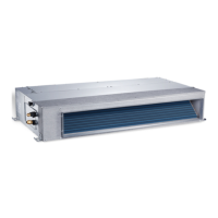
3.6.2 Connecting the indoor unit
The indoor unit is connected via a 4-wire communication cable. Use
cables of the type H07RN-F with sufficient conductor cross-section.
NOTICE
Material damage can be caused by connecting the indoor unit
incorrectly
Voltage is supplied to every indoor unit via the outdoor unit.
▶ Only connect the indoor unit to the outdoor unit.
Connecting the communication cable
▶ Open the clip locks and undo the screws of the top cover.
▶Fold up the top cover ( Fig. 31).
▶ Undo screws and remove cover of the interface panel [2].
▶ Guide the cable through the cable feed [1] on the rear of the indoor
unit.
▶ Secure cable to the strain relief and connect to the Handling terminals
L, N, S and
▶ Note assignment of wires to the terminals.
▶Close covers.
▶ Route the cable to the outdoor unit.
3.6.3 Connecting the outdoor unit
A power supply cable (3-wire) and the communication cable of the
indoor unit (4-wire) are connected to the outdoor unit. Use cables of the
type H07RN-F with sufficient conductor cross-section and protect the
mains power supply with a fuse.
▶ Secure the communication cable to the strain relief and connect to
the terminals 1(L), 2(N), S and (assignment of wires to terminals
same as indoor unit) ( Fig. 23 and 24).
▶ Attach 1 magnetic ring to the communication cable, as close as
possible to the outdoor unit.
▶ Secure power cable to the strain relief and connect.
– CL5000L ... E: terminals L, N and
– CL5000L ... E-3: terminals L1, L2, L3, N and
▶ Fasten cover for connections.
3.6.4 Connection as twin combination
With the twin combination, two indoor units are connected in series.
With the slave unit, terminal S is omitted. Instead of that, communication
takes place between he indoor units via terminals X, Y and E.
Key to Fig. 33 and 34:
IDU-M Master unit (indoor unit 1)
IDU-S Slave unit (indoor unit 2)
▶ Connect master unit as described in chapter 3.6.2.
▶ Connect save unit to the master unit via terminals L, N and
1)
.
▶ Connect master unit and slave unit additionally to terminals X, Y and
E via a communication cable. In doing so, earth the shield.
The central controller and twin combination both use the X/Y/E terminal.
For this reason, a decision must be made in advance if a twin
combination or central controller is installed.
3.6.5 Connecting external accessories
External accessories can be connected to the terminals listed below.
Table 8
To connect a gateway, observe the technical documentation of the
gateway and the connection accessories.
4 On-site configuration
4.1 DIP switch setting
WARNING
Risk to life from electric shock!
Touching live electrical parts can cause an electric shock.
▶ Before working on electrical parts, disconnect all phases of the
power supply (fuse/circuit breaker) and lock the isolator switch to
prevent unintentional reconnection.
All DIP switches have been configured before delivery. The default
setting is highlighted bold.
▶ Only professional maintenance personnel should change these
settings.
▶ Improper DIP switch settings may cause condensation, noise, or
unexpected system malfunction.
1) L=1(L) and N=2(N).
Connection Description / special features
CN23 On / Off contact switch
• Volt free terminal
• When using jumper connector, remove J6 next to
the connection.
•Open contact:
– Indoor unit off
– Remote control / room controller inactive
(CP in the display)
•Closed contact:
– Indoor unit on
– Remote control / room controller active
CN33 Alarm signal output
• Volt free terminal
• Connection, maximum 24 V DC, 500 mA
• Open contact: Alarm off
• Closed contact: Alarm on
CN40 Connection for room controller
CN43 External fan for supply of fresh air
• Integrated power supply for maximum 200 W or
1 A (relay recommended).
• External fan switches on / off simultaneously with
the fan of the indoor unit.
• In test mode or manual operation, the external
fan remains off.
 Loading...