Installation
Climate Line 5000i – 6721831693 (2022/05)
22
3.3 Unit installation
NOTICE
Incorrect assembly can cause material damage.
If the unit is assembled incorrectly, it may fall off the wall.
▶ Only install the unit on a solid flat wall. The wall must be capable of
supporting the weight of the unit.
▶ Only use screws and wall plugs that are suitable for the wall type and
weight of the unit.
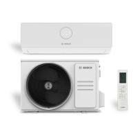
3.3.1 Installing the indoor unit
▶ Open the box at the top and lift the indoor unit out and up ( Fig. 6).
▶ Place the indoor unit with the moulded parts of the packaging face
down ( Fig. 7).
▶ Undo screw and remove the mounting plate on the rear of the indoor
unit.
▶ Determine the installation location, taking the minimum clearances
into consideration ( Fig. 2).
▶ Attach the mounting plate centrally with a screw and wall plug to the
wall and level out ( Fig. 8).
▶ Fasten the mounting plate with a further four screws and wall plugs so
that the the mounting plate lies flat on the wall.
▶ Drill wall outlet for the piping (wall outlet should be behind the indoor
unit as a recommendation Fig. 9).
▶ Change the position of the condensate pipe if necessary
( Fig. 10).
The pipe fittings on the indoor unit are generally located behind the
indoor unit. We recommend extending the pipes before mounting the
indoor unit.
▶ Establish pipe connections as described in Chapter 3.4.
▶ Bend the piping in the required direction if necessary, and knock out
an opening on the side of the indoor unit ( Fig. 12).
▶ Route the piping through the wall and attach the indoor unit to the
mounting plate ( Fig. 13).
▶ Fold up the top cover and remove one of the two filter elements
( Fig. 14).
▶ Insert the filter which is included in the scope of delivery into the filter
element, and mount the filter element again.
If it is necessary to take the indoor unit off the mounting plate:
▶ Pull the underside of the casing down in the area of the two recesses
and pull the indoor unit forwards ( Fig. 15).
3.3.2 Installing the outdoor unit
▶ Place the box so it is facing upwards.
▶ Cut and remove the packing straps.
▶ Pull the box up and off and remove the packaging.
▶ Prepare and mount a floor or wall mounting bracket, depending on
the type of installation.
▶ Mount or hang the outdoor unit using the anti-vibration coupling for
the feet which is supplied with the unit or is provided on site.
▶ When installing on the floor or wall mounting bracket, attach the
supplied drainage elbow and gasket ( Fig. 16).
▶ Remove the cover for the pipe connections ( Fig. 17).
▶ Establish pipe connections as described in Chapter 3.4.
▶ Mount the cover for the pipe connections again.
3.4 Pipework connection
3.4.1 Connecting refrigerant lines to the indoor and outdoor unit
CAUTION
Discharge of refrigerant due to leaky connections
Refrigerant may be discharged if pipe connections are incorrectly
installed.
▶ When reusing flared joints, always fabricate the flared part again.
Copper pipes are available in metric and imperial sizes, the flare nut
thread is however the same. The flared fittings on the indoor and outdoor
unit are intended for imperial sizes.
▶ When using metric copper pipes, replace the flare nuts with nuts of a
suitable diameter ( Tab. 6).
▶ Determine pipe diameter and length ( Page 21).
▶ Cut the pipe to length using a pipe cutter ( Fig. 11).
▶ Deburr the inside of the pipe at both ends and tap to remove swarf.
▶ Insert the nut onto the pipe.
▶ Widen the pipe using a flaring tool to the size indicated in the tab. 6.
It must be possible to slide the nut up to the edge but not beyond it.
▶ Connect the pipe and tighten the screw fitting to the torque specified
in the tab. 6.
▶ Repeat the above steps for the second pipe.
NOTICE
Reduced efficiency due to heat transfer between refrigerant pipes
▶ Thermally insulate the refrigerant lines separately.
▶ Fit the insulation on the pipes and secure.
Table 6 Key data of pipe connections
External diameter of
pipe Ø [mm]
Tightening torque [Nm] Flared opening diameter
(A) [mm]
Flared pipe end Pre-assembled flare nut
thread
6.35 (1/4") 18-20 8.4-8.7 3/8"
9.53 (3/8") 32-39 13.2-13.5 3/8"

 Loading...