Robert Bosch Engineering and Business Solutions Private Limited | September 19, 2020
5 General Info
• Sensor signal wires should be separated from both actuator signals and ignition switching signals.
• Correct fuse rating as per the system load to be calculated by the OEM and used on Battery positive supply.
• Calculation for their ratings will be responsibility of the customer.
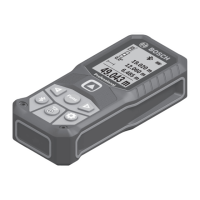
• Twisted pair wires should be used for CAN signals (Figure 3).
• For CCU power ground, multi-point grounding on chassis is recommended.
• Before fixing the ground wires to the chassis of vehicle, paint or any insulating material should be removed and the
surface should be cleaned to ensure proper ground connection.
• Fasteners with serrated washers to be used for fixing the ground cables to chassis.
Wiring
If necessary, wires of type FLR (R = reduced thickness of insulation) must be used.
It is recommended to use constantly insulator copper strands as per DIN 72551 or the newer
automotive norms LV112.
Mechanically unloaded cables can also be connected as wires with reduced thickness of insulation
(FLX or FLKr wiring).
As per DIN 40621, the cables should be laid in a cable protection sleeve.
Wiring harness layout in the vehicle - Sharp edges in the wiring layout should be avoided. The wiring
and primarily the plug connections must be protected against direct water or spray mist.
6 Pin-Out details
The different connectors and their pin-out details are discussed in the below sections
6.1 Main Connector
Digital : Output - High Side
6.2 RF Connector
PIN NO SIGNAL NAME
1
Antenna Port
2
Main Antenna Port
3
Antenna Port
Figure 3 Wiring in iTraMS
 Loading...