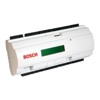
D1255TD Installation Instructions
74-06859-000-D Page 2 © 2004 Bosch Security Systems
D1255TD
2.0 Specifications
Table 1: Wiring Connections
Table 2: Panel Compatibility Chart
Power
•Nominal 12 VDC supplied by the panel
Current Required
•Idle: 104 mA, armed or disarmed.
•Maximum: 206 mA, with command center lighted and warning tone ON.
Wiring
•4-wire expansion cable supplies Data In, Data Out, +12 VDC, and Common.
•Maximum resistance on the conductors connected to SDI BUS A and SDI BUS B is 25 Ω.
Dimensions (HxWxD)
•4.56 in. x 8.15 in. x 0.816 in. (11.6 cm x 20.7 cm x 2.1 cm)
Color
•Warm Gray
Display
•Sixteen-character vacuum fluorescent display. Each character is a fourteen-segment unit.
•Soft blue color
Operating Temperature
•+32° to +122° F (0° to +50° C)
Relative Humidity
•5 to 85% @ +86°F (+30° C)
4 Wire Flying Leads from
D9112 and D7212
D1255TD Flying Leads
DATA BUS B (30) To Data Out (Green)
DATA BUS A (31) To Data In (Yellow)
POWER + (32) To 12 VDC (Red)
COMMON – (29) To Common (Black)
Control Panel
Command Center
D7212 D9112
D1255TD Supervised 8 8
D1255TD Unsupervised 32 32

 Loading...
