1 689 989 473 | 2021-08-24 Robert Bosch GmbH
42:
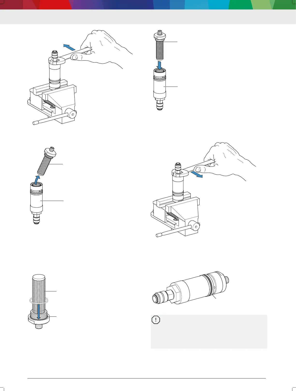
Loosening the lter housing
3.
Unscrew the test oil lter (1) from the lter housing
(2) and dispose of it (see 26 "Disposal" ).
43: Removing the test oil lter
4.
Flush the lter housing with clean test oil.
---Separator---
5.2.4.3
Installing the lter insert
1. Pull the provided O-Ring (24 x 1.5) (2) over the new
lter insert (1). The second O-Ring (12 x 2) included
in the scope of delivery will be needed later in the
installation of the inlet lter.
44: Test oil lter with O-ring
2.
Screw the lter insert (1) into the lter housing (2).
45:
Installing the test oil
lter
3.
Clamp the inlet lter into a vise with the connection
threads facing down.
4.
Tighten the lter housing with a torque wrench.
Tightening torque = 20 Nm
46: Tightening the lter housing
---Separator---
5.2.4.4 Installing the inlet lter
1.
Inspect the O-ring (1) on the inlet lter. Replace the
O-ring (28 x 2 mm) if it is defective.
47:
Inlet lter with O-ring
Fluff or dirt particles on the inlet lter body or on
the threads can nd their way into the ow meter
and block the measuring mechanism. Flow me‐
ters with a blocked measuring mechanism are ex‐
cluded from the warranty. Only screw a clean in‐
let lter into the measurement channel.
2.
Swivel down the inlet lter by the threaded connec‐
tion to immerse it in clean test oil.
3.
Remove the inlet lter, and allow it to drip off. Do
not use a cloth or the like to dry the inlet lter.
en | 22 | DCI 700
 Loading...