Installation Instructions
DS415i Photoelectric Intrusion
Detection System
1.0 General Information
Description:
The DS415i is a pulsed active infrared photoelectric intrusion detection
system designed to provide an alarm activation upon the detection of
an intruder passing through its beam. It consists of a separate
Transmitter and Receiver and is capable of coverage ranges up to
500 ft. (150 m). The Transmitter emits an invisible, pulsed infrared
beam which is received by the Receiver. If an intruder passes between
the Transmitter and Receiver, causing a beam blockage for a minimum
of 55 ms, the Receiver will indicate an alarm. The DS415i receiver
and transmitter are intended to be mounted indoors only.
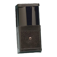
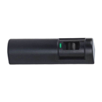
Peaking Voltage
Test Pins
Tamper Switch
Terminal Strip
Alarm LED
Margin Test Switch
Optical Module
Locking Lever
Battery
Pins
Specifications:
• Input Power: 8 to 14.5 VDC or 12 VAC.
NOTE: For DC input applications connect the unit only to a UL Listed
power supply or control unit capable of providing at least 4 hours
of standby time. For UL certificated, AC input applications the
TR12 transformer and P333 battery pack shall be used.
The model DS415iDC detectors are identical to the model
DS415i except the DS415iDC is intended to be connected to
a 12 VDC power source. The power source should only be a
UL Listed power supply or control unit within the range of 8 to
14.5 VDC.
Since the DS415iDC does not contain an internal standby
battery, the power source should be capable of providing at
least 4 hours of standby time in the event primary power is lost.
• Current Draw: Transmitter - 8 mA @ 12 VDC.
68 mA RMS with battery.
Receiver - 33 mA @ 12 VDC.
95 mA RMS with battery
• Range: 500 ft. (150 m).
• Alarm Output: Form "C" Rated at 125 mA @ 28 VDC.
• Tamper Output: Normally Closed Rated at 125 mA @
28 VDC.
• Temperature: Storage and operating temperature range
is 0°F to +120°F (–18°C to +49°C). For UL
installations the operating range is +32°F
to +120°F (0°C to +49°C), indoor use.
• Optional Accessories: TR12 Transformer, AL402
Alignment light, P333 Standby
Battery, C6000 Test Cord,
AE405 splash Resistant
Enclosure, M402A Mirror.
The AE405 and M402A shall not be used in UL Certificated
Installations.
2.0 Mounting
• Choose a location where an intruder entering the area will have to
cross between the Transmitter and the Receiver.
• Mounting surface should be rigid, and selected as to offer a clear
line of sight between the Transmitter and Receiver.
• Remove the cover of the Transmitter and, using the back of the
chassis as a template, locate and mark the four keyed mounting
slots on the mounting surface.
• Prestart the mounting screws in the mounting surface, attach and
secure the chassis to the mounting surface.
• Repeat the mounting procedure using the Receiver.
3.0 Wiring
•
Wire the Transmitter and Receiver as shown.
Receiver Wiring
Transmitter Wiring
Alarm
Tamper
Input Power
8 - 15 VDC
or 12 VAC
-+
1234567
1234
Input Power
8 - 15 VDC
or 12 VAC
-+
Retransmission
Circuit
E
O
L
1 K
Ω
End of Line
Resistor
Alarm Retransmission Circuit Information:
The Transmitter allows connection of normally open or normally
closed contacts to a supervised alarm retransmiss circuit. Alarm
retransmission allows dry contact devices such as door or window
contacts to be wired into the Transmitter using it as a relay path to
the Receiver without additional wiring to the Control Panel.
Retransmission Wiring:
34
E
O
L
1 KΩ EOL
Resistor
Alarm Alarm
N/O
N/CN/C
N/O
Transmitter Terminals