EasyManua.ls Logo

Bosch DS924i - User Manual

Bosch DS924i
4 pages
Print Icon
To Next Page IconTo Next Page
Loading...
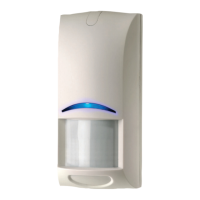
INSTALLATION INSTRUCTIONS
Learn Mode (LM) DS924i /DS924iP
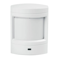
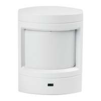
Wireless PIR Motion Sensor
A Passive Infrared (PIR) Motion Sensor is designed to detect movement in
the interior of a structure by sensing the Infrared energy emitted from the
human body as it moves across the Sensor’s field of view. When motion is
detected the unit sends an alarm signal to the Control Panel. The DS924i/
DS924iP are high performance PIR Motion Sensors which use advanced
signal processing to provide outstanding catch performance and
unsurpassed false alarm immunity.
1.0 Specifications
General
Power supplied by 3.6 VDC Lithium Battery. Saft LS14250 (0.85 AH,
2/3AA battery).
Typical current draw is 12 micro-amps with LED disabled.
Typical battery life is 5 years.
Operating temperature range of +32°F to +120°F (0°C to +49°C)
PIR Motion Sensor
Coverage area 35 ft. (10.7 m) by 40 ft. (12 m) for Standard and Pet
Avoidance lenses.
Optional Lens Kits available in packs of three (see Page 4).
Internal coverage pointability +2° to -10° Vertical and ±10° Horizontal.
Masking kit provided to block portions of coverage area.
Field selectable sensitivity options of Standard, Intermediate, or High.
Three minute transmitter lockout time after alarm extends battery life.
Timed Walk Test Mode automatically disables LED after setup to extend
battery life.
Cover activated Tamper indication. Optional wall activated Tamper is
included.
RF Transmitter
Integral RF transmitter capable of transmitting at least 500 feet open air.
(Actual acceptable transmitter range should be verified for each
installation).
Transmits low battery report (trouble) to the Control Panel.
Transmits supervisory signal to the Control Panel every 64 minutes.
Intended for use with listed compatible ITI Learn Mode control panels.
2.0 Installation Guidelines
Keep all sensors within 100 ft. (30.4 m) of the Control Panel. The 100
foot (30.4 m) distance recommendation is given as a starting guideline.
The LM PIR Transmitter has an open air range of at least 500 ft. (152 m),
but the installation environment may influence this range.
Mount the sensor so there is a reference point (such as a wall) at the
end of its detection pattern.
Mount the sensor so that an intruder will most likely walk across the
detection pattern, see Figure 1.
Mount the sensor between 6.5 (2 m) and 10 ft. (10.7 m) above the floor.
(Between 3 (1 m) and 5 ft (1.5 m) for Pet Avoidance Lens).
Mount on an insulated outside wall facing in.
Mount on a surface which is rigid and free from vibration.
Do Not:
Mount in direct sunlight.
Aim at air conditioners, heat vents, wood stoves, fireplaces, intermittent
heat sources, etc., see Figure 2.
Aim at solar heated walls or uninsulated metal walls.
Aim at normally moving objects (ceiling fans, pets, etc.), see Figure 2.
Mount the sensor where it can be exposed to moisture.
Mount in locations where the temperature may be outside the sensor’s
operating limits of +32°F to +120°F (0°C to +49°C).
Mount in areas with large metallic surfaces (e.g. heating ducts) or
electrical wiring which may inhibit the sensor’s RF signals from reaching
the Control Panel.
Mount in areas where the coverage may be blocked by any temporary
items such as boxes or freight.
3.0 MOUNTING
Surface or Corner Mounting (without swivel bracket)
Remove the sensor’s cover by gently inserting a screwdriver into the
notch at the bottom of the cover.
Completely loosen the mounting base locking screw.
Remove the mounting plate from the enclosure by prying it up and out
from the bottom.
Punch out 2 appropriate holes in the mounting plate (for surface or
corner applications).
If the wall tamper function is required, remove the rectangular knockout.
Locate the small spring in the hardware kit. Hold the PIR base so the
battery is visible. Place the spring on the black plastic shaft of the wall
tamper switch just below the battery.
Remove the wall tamper bypass jumper located next to the walk test
switch. NOTE: The wall tamper can not be used when corner mounting.
Question and Answer IconNeed help?

Do you have a question about the Bosch DS924i and is the answer not in the manual?

Summary

Sensor Specifications

General

General specifications for the PIR motion sensor, including power, current draw, battery life, and operating temperature.

PIR Motion Sensor

Details on PIR motion sensor coverage, optional lenses, internal adjustability, sensitivity, and tamper features.

RF Transmitter

Information on the RF transmitter's range, low battery reports, supervisory signals, and compatibility.

Installation Guidelines

Mounting Instructions

Surface or Corner Mounting

Instructions for mounting the sensor directly to a surface or in a corner without using a swivel bracket.

Programming the Sensor

Programming General Guidelines

Basic steps for programming the sensor, including control panel mode and tamper switch usage.

Walk Testing Setup

Sensitivity Selection

Sensor Testing Procedures

Pattern Testing

Procedure for testing the sensor's detection pattern and LED activation during Walk Test Mode.

RF Transmitter Testing

Steps to determine the actual RF transmitter range using the Control Panel's Dealer Sensor Test.

Final Testing Procedures

How to perform final testing by simulating environmental conditions and verifying alarms.

Maintenance and Battery

Battery Installation and Replacement

Guidelines for proper battery installation and post-installation waiting period before activation.

Pet Avoidance Lens Guidelines

Coverage Masking with Labels

Instructions for using masking labels to block specific zones or segments of the sensor's coverage.

Overview

The DS924i/DS924iP is a Passive Infrared (PIR) Motion Sensor designed to detect movement within an interior space by sensing the infrared energy emitted by the human body. When motion is detected, the sensor transmits an alarm signal to a compatible control panel. These models are high-performance PIR motion sensors that utilize advanced signal processing to provide excellent catch performance and minimize false alarms.

Function Description:

The primary function of the DS924i/DS924iP is to detect intruders by sensing changes in infrared energy within its field of view. Upon detection, it sends an alarm signal to a connected control panel. The sensor is designed to be used with listed compatible ITI Learn Mode control panels.

Important Technical Specifications:

  • Power: Supplied by a 3.6 VDC Lithium Battery (Saft LS14250, 0.85 AH, 2/3AA battery).
  • Current Draw: Typical current draw is 12 micro-amps with the LED disabled.
  • Battery Life: Typical battery life is 5 years.
  • Operating Temperature Range: +32°F to +120°F (0°C to +49°C).
  • Coverage Area (PIR Motion Sensor):
    • Standard and Pet Avoidance lenses: 35 ft. (10.7 m) by 40 ft. (12 m).
    • Optional Lens Kits are available.
  • Internal Coverage Pointability: +2° to -10° Vertical and ±10° Horizontal.
  • Masking Kit: Provided to block specific portions of the coverage area.
  • Sensitivity Options: Field selectable (Standard, Intermediate, or High).
  • Transmitter Lockout Time: Three minutes after an alarm, to extend battery life.
  • Timed Walk Test Mode: Automatically disables the LED after setup to extend battery life.
  • Tamper Indication: Cover-activated tamper is included. An optional wall-activated tamper is also available (cannot be used with corner mounting).
  • RF Transmitter Range: Integral RF transmitter capable of transmitting at least 500 feet in open air. Actual acceptable range should be verified per installation.
  • Low Battery Report: Transmits a low battery report (trouble) to the Control Panel.
  • Supervisory Signal: Transmits a supervisory signal to the Control Panel every 64 minutes.

Usage Features:

Installation Guidelines:

  • Placement:
    • Keep all sensors within 100 ft. (30.4 m) of the Control Panel (this is a guideline; open-air range is at least 500 ft. (152 m), but environmental factors can influence it).
    • Mount the sensor between 6.5 ft. (2 m) and 10 ft. (10.7 m) above the floor for standard lenses.
    • For Pet Avoidance Lens, mount between 3 ft. (1 m) and 5 ft. (1.5 m) above the floor.
    • Mount on an insulated outside wall facing inward.
    • Mount on a rigid, vibration-free surface.
    • Position the sensor so an intruder is most likely to walk across the detection pattern.
    • Ensure a clear line of sight across the protected room for pet avoidance.
    • For best results with pet avoidance, install the sensor no lower than twice the height of the pet.
  • Avoid:
    • Direct sunlight.
    • Aiming at air conditioners, heat vents, wood stoves, fireplaces, or other intermittent heat sources.
    • Aiming at solar-heated walls or uninsulated metal walls.
    • Aiming at normally moving objects (e.g., ceiling fans, pets).
    • Exposure to moisture.
    • Locations where temperatures are outside the operating limits.
    • Areas with large metallic surfaces or electrical wiring that may inhibit RF signals.
    • Areas where coverage may be blocked by temporary items.

Mounting Options:

  • Surface or Corner Mounting (without swivel bracket):
    • Remove the cover and mounting plate.
    • Punch out appropriate holes in the mounting plate.
    • For wall tamper, remove the rectangular knockout and place the small spring from the hardware kit on the black plastic shaft of the wall tamper switch.
    • Remove the wall tamper bypass jumper. Note: Wall tamper cannot be used with corner mounting.
    • Secure the mounting plate to the wall using #6 x 1" wood screws.
    • Attach the PIR base to the mounting plate and tighten the locking screw.
    • Replace the cover, engaging the top first, then securing the bottom latch. A small screw can be used to lock the cover for added security (requires knocking out a screw hole in the bottom of the cover).
  • Swivel Bracket Mounting:
    • Mark holes using the swivel bracket as a template.
    • Corner mount tabs can be removed if not mounting in a corner.
    • Secure the swivel bracket to the wall using #6 x 1" wood screws.
    • Attach the mounting plate to the swivel bracket using a #6 x 5/8" machine screw.
    • Aim the mounting plate and tighten the screw. Note: Wall tamper cannot be used with swivel bracket mounting, and it may reduce range and create dead zones.

Programming:

  • Put the Control Panel in program mode.
  • Trip the sensor's tamper switch by removing and replacing its cover.
  • Refer to the Control Panel installation manual for specific instructions.

Walk Testing Setup:

  • Lens Change: Remove the sensor's cover, pull out the installed lens, and insert the new lens with the smooth side facing out and the grooved side facing in. The notch indicates the top center.
  • Coverage Adjustment: The coverage pattern can be aimed by moving the circuit board and/or lens. Vertical angle can be adjusted between -10° and +2° by loosening and sliding the Vertical Adjust Screw. Horizontal angle can be shifted ±10° by rotating the lens.
  • Sensitivity Selection: Locate the sensitivity pins and move the shorting jumper to the desired pair of pins (Standard, Intermediate, or High). If the jumper is not used or placed incorrectly, the sensor defaults to Intermediate.
    • Standard: Recommended for Broad coverage, most tolerant of environmental extremes.
    • Intermediate: For Long Range or Barrier type lenses, or where an intruder covers only a small portion of the protected area; tolerates normal environments.
    • High: For quiet environments without thermal and illumination transients; fastest response to intruder signals.

Testing:

  • Pattern Testing: Press the Walk Test Switch to start a 90-second Walk Test Mode. Activity in the coverage pattern triggers an alarm and LED activation, extending the mode by 90 seconds. Walk test across the pattern to determine boundaries. Excessive use of Walk Test Mode reduces battery life.
  • RF Testing: Perform a Dealer Sensor Test: Remove cover, press Walk Test Switch, replace cover. Enter Dealer Sensor Test Code on the Control Panel. Move across the detection pattern until the LED turns on. Stop motion. Note the number of siren beeps (should be 7-8). Relocate and retest if fewer than 6 beeps.
  • Final Testing: Turn on all heating and air conditioning sources. Stand away from the sensor and outside the coverage pattern, watching for alarms.
  • The LED flashes to indicate the end of Walk Test Mode after 90 seconds of no activity. After Walk Test Mode ends, an alarm can only be transmitted after three minutes (lockout time) to reduce unnecessary RF transmissions and extend battery life.

Pet Avoidance Lens Guidelines:

  • Mounting height: 3 to 5 feet.
  • Clear line of sight across the room.
  • Install no lower than twice the pet's height.
  • Ensure the field of view is free of furniture or objects pets could climb on.

Coverage Masking:

  • Masking labels are provided to match lens segments.
  • Determine which zone/segment needs masking.
  • Peel the mask label and apply to the inside of the lens segment to be blocked.

Maintenance Features:

  • Annual Verification: At least once a year, verify the range and coverage for proper operation.
  • Daily Verification: Instruct end-users to walk through the far end of the coverage pattern to verify an alarm output prior to arming the system.
  • Battery Installation: The sensor is normally shipped with its battery installed. If replacing, observe proper polarity. Wait at least 5 minutes after installing a new battery before activating Walk Test Mode.

Bosch DS924i Specifications

General IconGeneral
BrandBosch
ModelDS924i
CategoryAccessories
LanguageEnglish

Related product manuals