Page 2 © 2004 Bosch Security Systems DS924i/P Installation Instructions
• Using the mounting plate as a template, mark the location of the required
holes on the mounting surface.
• For installation on drywall or plaster, drill a 1/8" pilot hole to determine if a
wall anchor is required.
• Secure the mounting plate to the wall with the #6 x 1" wood screws
provided.
• Skip to “Attaching the Enclosure."
Swivel Bracket Mounting
• Using the swivel bracket as a template, mark the location of the required
holes on the mounting surface.
• If not mounting in a corner, the corner mount tabs may be removed
(Figure 6).
• For installation on drywall or plaster, drill a 1/8" pilot hole to determine if a
wall anchor is required.
• Secure the swivel bracket to the wall with the #6 x 1" wood screws
provided.
• Attach the mounting plate to the swivel bracket using the #6 x 5/8"
machine screw provided.
• Aim the mounting plate in the desired direction and tighten the screw.
NOTE: The wall tamper switch can not be used when mounting with the
swivel bracket. Use of the swivel bracket may reduce range and dead
zones.
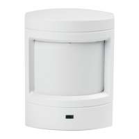
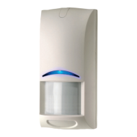
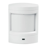
Attaching the Enclosure
• Attach the PIR base to the mounting plate and tighten the mounting plate
locking screw.
• Replace the cover, engaging the top first then securing the bottom latch.
• For added security, the cover may be locked to the base latch using the
small screw provided. The screw hole in the bottom of the cover must
be knocked out prior to replacing the cover.
4.0 Programming
General Guidelines
• Put the Control Panel in program mode.
• Trip the sensor’s tamper switch by removing its cover.
• Restore the tamper by replacing the sensor’s cover.
Refer to the appropriate Control Panel installation manual for specific
instructions on programming this device.
5.0 Walk Testing Setup
• If the correct lens is already installed, skip to the Sensitivity Selection.
• To change the lens, first remove the sensor’s cover.
• Remove the installed lens by grasping each side and pulling it away from
the lens frame.
• Replace with the appropriate lens by inserting the corners of the lens
behind the tabs in the lens frame.
• Install the new lens with the smooth side facing out and the grooved side
facing in.
• The notch indicates the top center of the lens.
• The coverage pattern may be aimed by moving the circuit board and/or
lens.
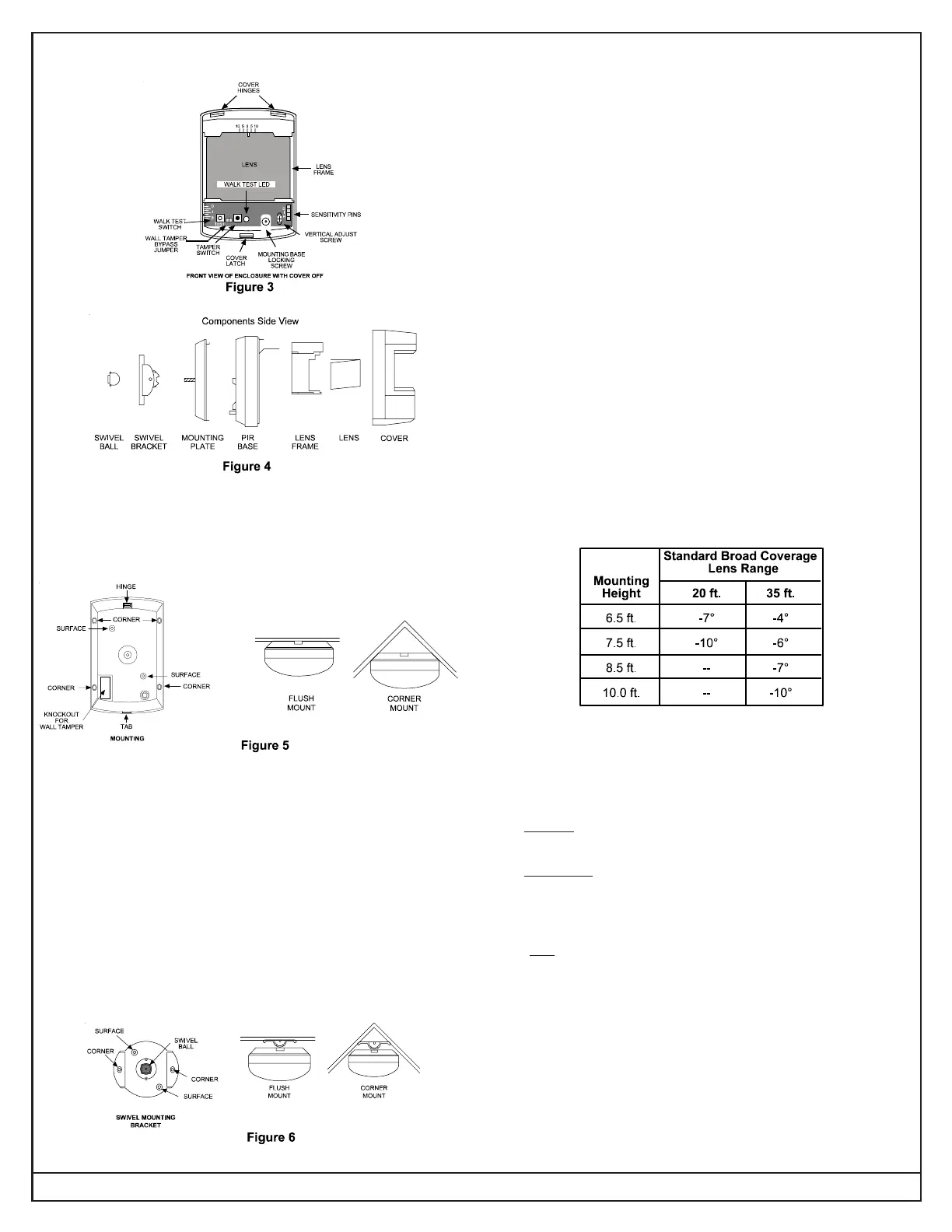
• Consult the pattern drawings on Page 4 and the following recommended
adjustment table.
6.0 Sensitivity Selection
• Locate the sensitivity pins. Move the shorting jumper to the appropriate
pair of pins.
• If the shorting jumper is not used or placed incorrectly, the sensor
defaults to Intermediate sensitivity.
Standard sensitivity is recommended for Broad coverage patterns.
This setting is the most tolerant of environmental extremes.
Intermediate sensitivity should be used for Long Range or Barrier
type lens patterns or for any location where an intruder is expected
to cover only a small portion of the protected area. This setting
tolerates normal environments.
High sensitivity should only be used in quiet environments
where thermal and illumination transients are not
anticipated. This setting has the fastest response to
intruder signals.
 Loading...