DS160/161
Request To Exit PIR sensors
Installation Instructions
1.0 Description
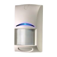
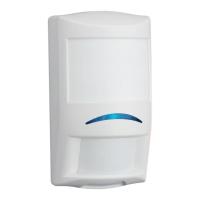
The DS160/161 is a passive-infrared (PIR) detector designed for request to exit (REX) interior applications. It is UL Listed as an access
control device under the UL 294 Standard.
The technology designed into the DS160/161 is based on the principal that all objects emit infrared energy. The warmer an object is, the more
infrared energy emitted. Its PIR technology allows the DS160/161 to detect the change in infrared energy that occurs when a person passes
through its field of view.
The DS160/161 has features such as Sequential Logic Input (SLI) to eliminate unauthorized entry. SLI allows you to arm the detector using
any dry contact device, such as a second detector, card reader, or the access control system. This provides better control for this type of
application.
A built-in sounder can be automatically activated if the door is propped open. The sounder can be controlled from any dry contact device. The
DS160/161 detection pattern provides dense C-shaped coverage ideal for most REX applications. In addition, complete pattern control
allows it to be adjusted to a single zone or placed over a doorknob, for example. There are fifteen possible coverage patterns to accommo-
date most applications. This, combined with the ability to monitor the door and intelligently control the lock, adds considerable security to
these types of applications.
The DS160/161 uses Motion Analyzer II signal processing to help prevent false activation due to environmental conditions. The relay output
consists of two Form “C” contacts that can be adjusted to latch from approximately 0.5 to 64 seconds. The latch time features two modes of
operation, resettable (where the relay timer will not time out as long as someone is in the field of view) and non-resettable (where the relay
will remain latched for a fixed period of time). The relay can also be programmed to fail safe or fail secure in the event of power loss.
The DS160/161 may either be ceiling or wall mounted, and its pattern may be aimed and/or masked for more effective use based upon
installation needs. It is not designed as a primary means of exit for emergency egress applications.
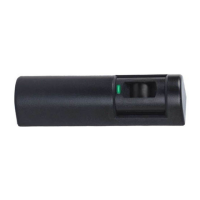
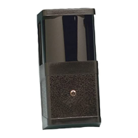
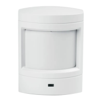
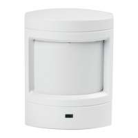
The DS160/161 is available in a light grey (DS160) or a black (DS161) enclosure along with an optional trim plate (light gray TP160 or black
TP161) that can cover a single gang box. Panic hardware must be used with this or any other egress device.
2.0 Specifications
• Input Power: 12 VDC to 30 VDC or AC
• Current Draw: 39 mA at 12 VAC, 76 mA at 30 VAC Alarm 39 mA at
12 VDC, 60 mA at 30 VDC Alarm 8 mA nominal
standby current
• Relay: Two Form “C” contact sets rated for 1 A each at
30 VDC or AC max for resistive loads.
• Sounder: 85 dB with adjustable volume
• Temperature: -20°F to +120°F (-29°X to +49°C). For UL
Listed installations, the temperature range
is +32°F to +120°F (0°F to +49°C)
.
•
Humidity: 0% to 95% non-condensing. 0% to 85%
non-condensing for UL Listed
installations
.
• Dimensions ( xWxD): 1.8 in. x 7 in. x 1.75 in.
(4.5 cm x 17.8 cm x 4.4 cm)
• Trim plate (HxW): Optional. TP160 (light gray); TP161 (black)
3 in. x 8.25 in. (7.6 cm x 21 cm)
3.0 Installation
3.1 Remove the cover using a small flat blade screwdriver.
Insert screwdriver
here
Bottom
of
unit
3.2 Rotate the detector clockwise to remove it from the
base.
3.3 Select a mounting location
Push to Ex it
Alarm will So und
Push to Exit
Alarm will Soun d
Push to Exit
Alarm will Sound
Push to Exit
Alarm will Sound
Above the
Door
On the Ceiling
Above
Double Doors