EasyManua.ls Logo

Bosch Rexroth CIMS Mk IV User Manual

Bosch Rexroth CIMS Mk IV
60 pages
To Next Page IconTo Next Page
Page #1 background imageLoading...
Page #1 background image
F 037 300 069 (2013.05.21)
1
Instruction manual
CIMS Mk IV
Bosch Rexroth B.V.
PO Box 32
5280 AA Boxtel
The Netherlands

Table of Contents

Question and Answer IconNeed help?

Do you have a question about the Bosch Rexroth CIMS Mk IV and is the answer not in the manual?

Bosch Rexroth CIMS Mk IV Specifications

General IconGeneral
BrandBosch
ModelRexroth CIMS Mk IV
CategoryAccessories
LanguageEnglish

Summary

2. General Information

2.1. Correspondence

2.2. Precautions

2.3. ATEX Certified CIMS Mk IV

2.3.1. General Notes

General safety notes for personnel working in hazardous areas with ATEX equipment.

2.3.2. ATEX Protection Type and Marking

2.3.3. Assembly

2.3.4. Installation

2.3.5. Commissioning

2.3.6. Inspection and Maintenance

3. CIMS Mk IV: Function, Characteristics and Scope of Delivery

3.1. Function

Explains how the Cylinder Integrated Measuring System (CIMS) works.

3.2. Characteristics

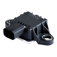
Lists the key features and capabilities of the CIMS Mk IV sensor.

3.3. Scope of Delivery

3.3.1. CIMS Mk IV Standard Version

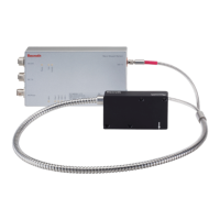
Lists the components included with the standard CIMS Mk IV version.

3.3.2. CIMS Mk IV ATEX Version

Lists the components included with the ATEX-certified CIMS Mk IV version.

4. Installation

4.1. Mounting CIMS on Cylinder

4.1.1. Phase 1: Configuration of Output Connection Position

Configuring the orientation of the output connection before mounting.

4.1.2. Phase 2: Check/Change the Cable Outlet

4.1.3. Phase 3: Mount New Cable Outlet

4.1.4. Phase 4: Installation onto the Cylinder

4.1.5. Removal from the Cylinder

4.2. Electrical Installation

4.2.1. Wiring

Requirements and recommendations for selecting and connecting the CIMS Mk IV cable.

4.2.2. Cable Termination

4.2.3. Shielding and Grounding

4.2.4. Internal Connector

4.2.5. External Connector/Connection

4.2.5.1 9-Pin Standard Connector

Assembly instructions for the 9-pin standard angled connector.

4.2.5.2 Ex d Cable Entry System

5. Operation

5.1. Startup

Steps to follow for powering up and starting the CIMS Mk IV after installation.

5.2. Output Signals and Accuracy

Details on the two output interfaces: RS422 incremental and RS485 diagnostic.

5.2.1. RS422 Incremental Position Output

Information on the RS422 quadrature encoder output and its specifications.

5.2.2. RS485 Diagnostic Output

6. Technical Data

6.1. Power Supply

Specifies the required power supply voltage and current for the CIMS Mk IV.

6.2. RS422 Incremental Position Output

Technical specifications for the RS422 incremental position output.

6.3. RS485 Modbus Diagnostic Output

Technical specifications for the RS485 Modbus diagnostic output.

6.4. Operating and Ambient Conditions

Details on operating temperature, humidity, and other environmental limits.

7. Accessories

7.1. Spare Part Kit

Information about the available spare part kit for the CIMS Mk IV.

7.2. CIMS Mk IV Cable

Details of the specific cable delivered by Bosch Rexroth for the CIMS Mk IV.

7.3. Connection Options

Describes various connection options like angled connectors and underwater connectors.

7.4. Signal Converters

Appendix A CIMS Mk VI Drawings

A.1 F 037 A00 002 CIMS Mk IV Standard Version (Non-ATEX)

Technical drawing for the standard, non-ATEX version of the CIMS Mk IV.

A.2 F 037 A00 004 CIMS Mk IV ATEX Version

Appendix B Drawing 3-033701 Mounting Bore Pattern on Cylinder

Appendix C Modbus Communication Protocol Description

C.1 Communication Setup

Details the fixed communication parameters for Modbus setup.

C.2 Sensor Startup Timing

Explains the sensor's startup sequence and timing after power-up.

C.3 General Error Messages

Lists general error codes sent by the CIMS Mk IV to the master.

C.4 Read Identification Data

C.4.1 Possible Error Messages

Lists possible error messages related to reading identification data.

C.4.2 Read Vendor Name (00H)

Procedure to read the vendor name from the CIMS Mk IV.

C.4.3 Read Customer Number (01H)

C.4.4 Read Product Version (02H)

C.4.5 Read Manufacturing Date (80H)

C.4.6 Read Serial Number (81H)

C.4.7 Read Order Number (90H)

C.4.8 Read Bootloader Identification Number (B0H)

C.4.9 Read Bootloader Version (B1H)

C.4.10 Read Application Software Identification Number (A0H)

C.4.11 Read Application Software Version (A1H)

C.4.12 Read Modbus Interface Version (A2H)

C.5 Sensor Event Management

C.5.1 Possible Error Messages

Lists possible error messages related to sensor event management.

C.5.2 Get Last Debug Detail (10H, E0FEH)

Service to retrieve details about the last occurred debug event.

C.5.3 Get Sensor Status (03H, E000H)

C.5.4 Read Event Memory (03H, E001H-E00AH)

C.5.5 Clear Event Memory (06H, E0FFH)

C.6 Measurement Data

C.6.1 Possible Error Messages

Lists possible error messages related to reading measurement data.

C.6.2 Get Current Position Since Last Power Up (03H, A010H)

Service to retrieve the current position since the last power-up.

C.6.3 Set Current Position Since Last Power Up (06H, A010H)

C.6.4 Get Operating Time (03H, A000H)

C.7 Configuration Data

C.7.1 Possible Error Messages

Lists possible error messages related to configuration data.

C.7.2 Get Modbus Baud Rate (03H, C000H)

C.7.3 Get Modbus Device ID (03H, C001H)

C.8 Routine Control

C.8.1 Possible Error Messages

Lists possible error messages related to routine control.

C.8.2 Sensor Reset (10H, F000H)

Service to perform a reset of the microcontroller on the sensor.

Appendix D Declaration of Conformity (EMC Directive 2004/108/EC)

Appendix E Declaration of Conformity (ATEX Directive 94/9/EG)

Related product manuals