F 037 300 069 (2013.05.21)
16
4.1.2. PHASE 2: CHECK / CHANGE THE CABLE OUTLET
As default the CIMS Mk IV standard (non-ATEX) is supplied with the 9-pin male connector chassis
or no connection (only a threaded hole) for the CIMS Mk IV ATEX version. If another connection is
needed (see Section 4.2.5), or for installation of an Ex d cable gland, Phase 2 and 3 will have to be
executed. If the default connection is suitable, Phase 2 and 3 can be skipped.
1. Unscrew the four M2,5 bolts (Bolt C) on the male socket,
2. Unscrew the four M6 bolts (Bolt D) on the housing cover,
3. Open the housing cover (the 2 threaded holes in the cover can be
used to push off the cover with 2 M6 bolts, see Figure 7) and let it
hang on the side of the housing. A cable fixed at the cover and at the
inside of the intermediate piece prevents that the cover can fall down,
4. Unscrew the two screws (Screw E) fixing the inner connector with its
mating connector (see Figure 9),
5. Remove / lift the inner connector from the header carefully, avoiding
any force from the header to the electronic circuit. If it is difficult to
reach the connector, it is possible to lift the intermediate piece from
the housing base after removing the four M6 bolts (Bolt B, Figure 5),
see Figure 8,
6. Unscrew the 8 screws (Screw F) and remove each wire from the
detached mating connector (see Figure 10),
7. Remove the male socket and the connected wires from CIMS Mk IV.
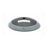
Figure 10: Inner connector side view.
Screw F (8x)
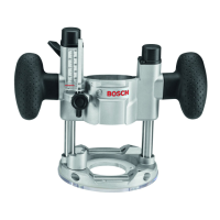
Figure 9: Inner connector top view.
Screw E (2x)
M5 internal grounding
point
Two pulling off screws
(M6) can be used on
the cover and on the
housing base to make
the removal easier.
Do not apply tension
force on the electrical
wires and make sure
the inside connector is
not damaged during
this operation.
O-rings could be
damaged during this
operation. They have
to be manipulated with
caution and replaced in
case of damage.
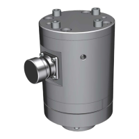
Bolt C
(4x)
Bolt D (4x)
2x M6
threaded
holes
2x M6
external
grounding
point
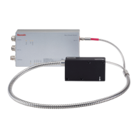
Figure 8: Intermediate piece lifted from housing base.
Inner connector
cable side
Connector
header on PCB
Screw F (8x)
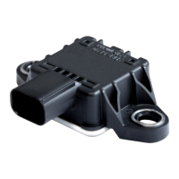
Figure 7: CIMS Mk IV cover and connector socket bolts.
 Loading...