F 037 300 069 (2013.05.21)
20
4.2.4. INTERNAL CONNECTOR
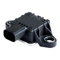
Inside the CIMS housing is a green 8-pin Phoenix connector, which is used to connect the
incoming cable, directly or via an external connector, to the CIMS electronics. The pin assignment
(Figure 16) of the internal connector is given in Table 1. How to remove or install a cable to the
internal connector is described in Sections 4.1.2 and 4.1.3.
4.2.5. EXTERNAL CONNECTOR / CONNECTION
Several connection types are available to connect the cable to the CIMS. To support this, the CIMS
housing is provided with a G½” threaded connection according DIN3852-2, together with four M2.5
tapped holes for a chassis connection (see drawing F 037 A00 002, Appendix A).
The type of connection depends on the application and the (expected) environmental conditions.
Please contact Bosch Rexroth for any additional information or advice.
CIMS Mk IV Standard version
At delivery from the factory, the CIMS Mk IV Standard version is delivered with a 9-pin male
connector chassis. The corresponding female connector has to be ordered separately. Section
4.2.5.1 describes the assembly instructions for the connector and the maintenance procedure. The
pin assignment of the standard connector corresponds with Table 1.
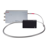
Other cable connection options are also available, like an underwater connector for applications
where the CIMS is submerged in water. For applications where the cable and or connection should
be protected from the environment, stainless steel protective piping can be delivered to protect
against mechanical damage. Section 7.3 gives more information about the different available
connection options which can be delivered by Bosch Rexroth.
CIMS MK IV ATEX version
At delivery from the factory, the CIMS Mk IV ATEX version does not
include an Ex d cable
gland, as the suitability of a cable gland is also depending on the type of cable used. In
section 4.2.5.2 the different selection criteria are given to select a proper cable entry
system for use in an ATEX zone 1 environment. Section 7.3 gives information about the Ex d
certified cable gland which can be delivered by Bosch Rexroth as an accessory.
Pin Signal
1 V+
2 GND
3 A
4 /A
5 B
6 /B
7 Modbus +
8 Modbus -
Table 1: Pin assignment internal/external connector.
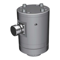
Figure 16: Internal connector top view.
 Loading...