DS160/161 Installation Instructions © 2004 Bosch Security Systems Page 5
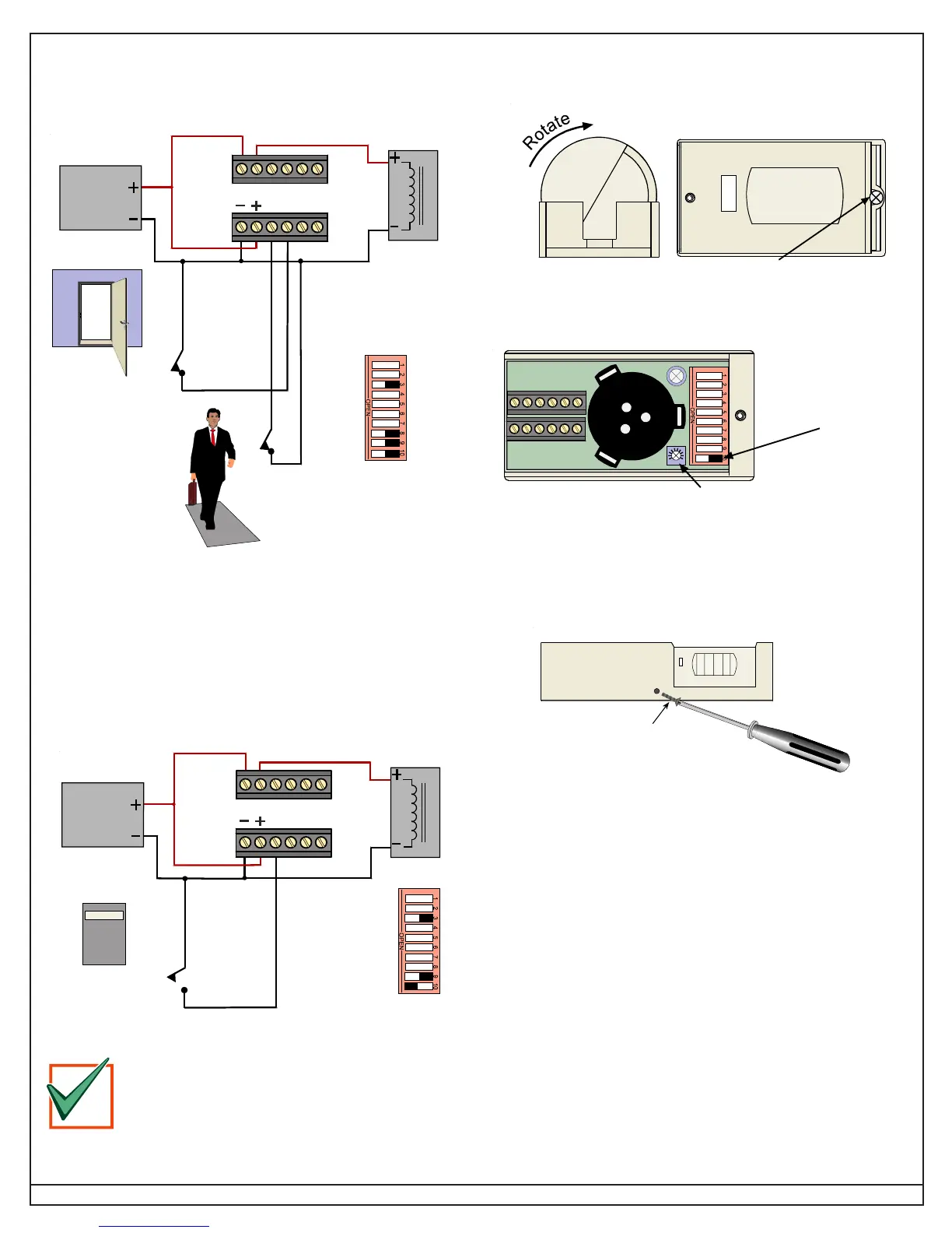
5.7.5 Wiring Example: Monitor Door Contacts (Second Option)
If the detector is activated but the door is not opened, the relay drops
out after 10 sec. If the detector is activated and the door opens, then
closes, the relay drops out after 2 sec. This prevents unauthorized
people from entering.
12-30 Volt
DC or AC
Power
Supply
Maglock
Relay contacts
shown with
Switch 3 ON
(Failsafe Mode)
Switch 8 is ON
(Door Secure
Mode)
Door Contacts
(
N
ormally
C
losed
contacts)
Floor Switches
or other inputs
NC C NO NC C NO
DRTT
5.7.6 Disabling the Request-To-Exit (Example 1)
The DS160/161 can be disabled by using Terminal R and an external
device such as an access control or burglar alarm system. When the
contact connected to Terminal R closes, the DS160/161 disables
after a 10-sec delay. The DS160/161 returns to normal operation as
described in
Section 5.7.3
after the contact closes.
12-30 Volt
DC or AC
Power
Supply
Maglock
Relay contacts
shown with
Switch 3 ON
(Failsafe Mode)
Switch 9 is ON and
Switch 10 is OFF
(Monitor External
Device Mode)
NC C NO NC C NO
D
RTT
Access Control
System
Contacts
Controlthispal, Inc
The NFPA 101 Life Safety Code
®
requires secured
doors to have a “manual release device that shall
result in direct interruption of power to the lock -
independent of the access control system
electronics”.
IMPORTANT
6.0 Complete Installation
6.1 Secure the detector inside base.
Secure by tightening the
lock-down screw.
Rotate the barrel to the
desired location.
6.2 Adjust the sounder volume.
To adjust the volume, turn the Volume Control with a screwdriver.
Turn clockwise to increase the volume, and counterclockwise to decrease.
To test the volume,
turn Switch 10 on
and apply power.
The sounder will turn
on as long as
Terminal R is open.
6.3 Replace the cover and secure with screw.
Use a drill to remove screw knockout in the cover only, then start
screw and tighten to secure.
Self-Tapping
Screw
(provided)