Page 2 © 2004 Bosch Security Systems DS160/161 Installation Instructions
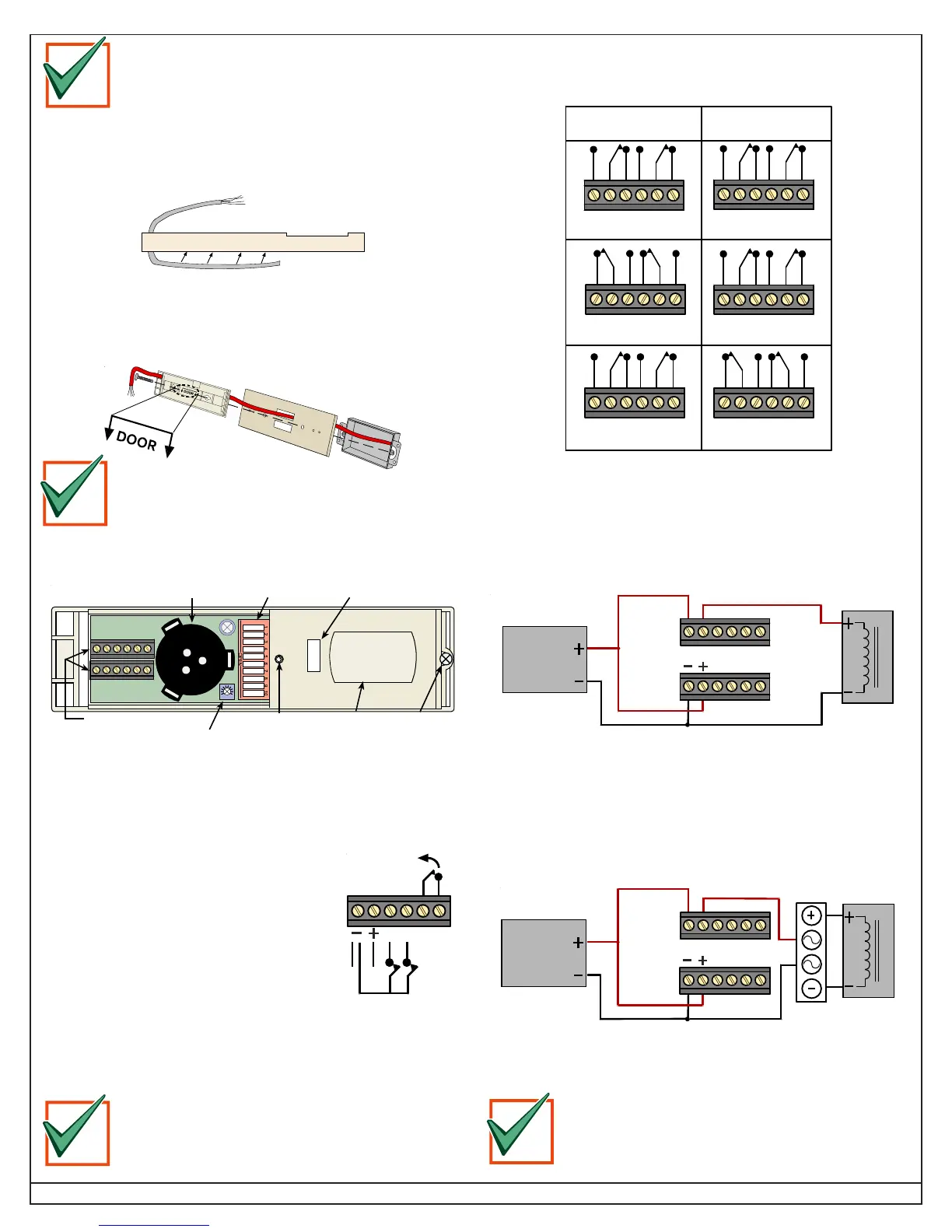
3.5 When using the optional trim plate (TP160 or TP161), run
the wiring through the trim plate and into the base before
mounting the base and trim plate onto a single gang
electrical box.
The arrows on the base indicate its correct mounting
orientation relative to the door.
3.4 Route the wiring through the base before mounting the
base to the wall or ceiling. See
Section 3.5
when using the
optional trim plate (TP160 or TP161).
4.2 Contact Output Wiring
The normal settings of the contact outputs change depending on the
setting of the Relay Mode Switch (S3). See
Section 5.3
.
Fail Safe
(Switch 3 On)
Fail Secure
(Switch 3 Off)
Power Off Power Off
Normal (No Motion)
Normal (No Motion)
Motion Detected
Motion Detected
NC C NO NC C NO NC C NO NC C NO
NC C NO NC C NO NC C NO NC C NO
NC C NO NC C NO
NC C NO NC C NO
Before you mount the unit, review
Section 7 Coverage
Patterns
for more information on the placement and
location of the DS160/161.
4.3 Wiring Examples
4.3.1 Basic Hookup
The basic hookup includes the DS160/161, a power supply, and a
magnetic lock. When the sensor sees motion, power is removed
from the magnetic lock.
12-30 Volt
DC or AC
Power
Supply
Maglock
Relay contacts shown with Switch 3 ON (Failsafe Mode) and Power On
NC C NO NC C NO
D
RTT
4.3.2 Spike Protection
Many magnetic locks and electric door strikes have built-in spike
protection (also be called diode protected). If your lock is not spike
protected, install a bridge rectifier, such as a KBL005, between the
relay contacts and the magnetic lock/door strike as shown below.
12-30 Volt
DC or AC
Power
Supply
Maglock
NC C NO NC C NO
D
RTT
Bridge
Rectifier
Relay contacts shown with Switch 3 ON (Failsafe Mode) and Power
On.
Failure to spike protect the detector can shorten the
life of the relay contacts.
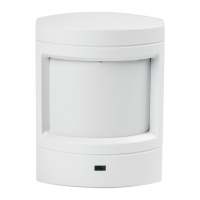
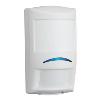
3.6 Note the location of detector features.
Wire Terminals
Sounder
Sounder
Volume
Control
DIP Switches
Tamper Switch
LED
Lens Lock-Down
Screw
IMPORTANT
4.0 Wiring
4.1 Power, Remote Input, Door Contacts, and Tamper
(-) Connect to the negative side of the power supply.
(+) Connect to the positive side of the power
supply. The voltage must be between
12 VAC and 30 VAC or DC.
(R) Terminal R is for Sequential Logic Input
(SLI), the keycard input or for remote control
of the sounder. The contact must be
Normally Closed (NC). See
Section 5.7
for
more information.
(D) Terminal D allows the detector to monitor
door contacts. See
Sections 5.6
and
5.7
for more information. If used, these
contacts must be Normally Closed (NC) door contacts. Do Not
share these contacts with any alarm systems.
(T) and (T) Normally Closed (NC) Tamper contacts.
Before wiring the unit, review
Wiring Examples
in
Sections 4
and
5
for more information on the wiring
of the DS160/161.
D
RTT
IMPORTANT
IMPORTANT
IMPORTANT