Installation Instructions
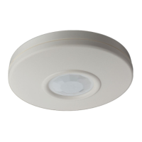
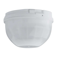
DS936 Ceiling Mount Passive Infrared
Intrusion Detection
1.0 General Information
The DS936 is a Low Profile Ceiling Mount Passive Infrared Intrusion Detector,
which uses alternate polarity pulse count. It uses a pointable Fresnel lens to
provide up to 24 ft (7.2 m) of coverage and may be mounted on the surface,
or semi-flush directly to a ceiling or a standard octagonal electrical box.
INPUT POWER: 10 to 15 VDC non polarized; 15 mA @ 12 VDC.
STANDBY POWER: No internal standby battery. Unit is intended to be connected to
DC power sources capable of supplying standby power in the event primary power
fails. 15 mA-H required for each hour of standby time needed.
MOUNTING HEIGHT: 7 to 12 ft. (2.1 to 3.7 m) on ceiling.
COVERAGE: Provides 360° coverage pattern. (Coverage is approximately 2 times
the mounting height, see pattern drawing on page 2.)
SENSITIVITY: Adjustable for Standard, Intermediate, or High.
POINTABILITY: ±15° rotationally by moving lens.
ALARM RELAY: Normally Closed operation and protected by a 4.7 ohm resistor in
series with the relay contact. Reed relay with contacts rated at 28 VDC, 125 mA maxi-
mum for DC resistive loads.
TAMPER: Normally Closed tamper switch rated at 28 VDC, 125 mA.
LED OPERATION: Dip Switch On/Off Selectable.
TEMPERATURE: The storage and operating temperature range is -20°F to +120°F
(-29°C to +49°C).
For UL Listed Requirements, the temperature range is +32° to +120°F
(0° to +49°C).
OPTIONS: TC6000 Test Cord.
View with Cover Off
2.0 Mounting
THINGS TO AVOID/REMEMBER
AVOID
• Direct hot and/or cold drafts • Windows • Small Animals
• Air Conditioning Outlets • Heat Sources • Direct Sunlight
REMEMBER
• Won’t detect through glass
• Best catch performance is across the pattern
• When using two or more detectors, cross the patterns for best coverage
The DS936 is designed to be surface mounted directly on the ceiling or recess mounted
to any 3 1/2 inch (88.9 mm) standard octagonal box.
• Select a location that is most likely to intercept an intruder moving beneath and
across the coverage pattern. Recommended mounting height is 7 ft. to 12 ft. (2.1 m
to 3.7 m).
NOTE: Mounting surface should be solid and vibration free (e.g., Drop tiles should
be secured if drop ceiling is used as an air return system for HVAC sys-
tems).
• Remove the top cover by gently prying it from the base with the blade of a screw
driver.
• Route wiring through the wire entrance located near the terminal strip.
• Using the enclosure as a template, mark the location for the mounting screws, and
prestart the mounting screws.
• Firmly mount the detector to the mounting
surface.
Recess Mounting With Octagonal Box:
• To mount the DS936 to a 3 1/2 inch (89 mm) stan-
dard octagonal box, remove the circuit board holder
from the base by prying holder tabs out with your
thumbs and pushing the board holder assembly out
with your index fingers.
The base may be discarded or saved for possible
future use.
• Route wiring as necessary through the box and into
the wire entrance.
• Mount the circuit board holder assembly to the box.
Recess Mounting Without Electrical Box:
The DS936 may be recess mounted without the use of an octagonal
box by using the supplied flush mount ring.
• Remove the board holder assembly from the base by prying
holder tabs out with your thumbs and push the board holder
assembly out with your index fingers.
• Using the inside cutout of the flush ring as a template, prepare
an opening 2-3/4" by 2-5/8" (70 x 67 mm) wide in the mounting surface.
• Route wiring through opening and flush mount ring.
• Place the flush mount ring over the opening and bend the support tabs into the
opening and around the mounting surface so that the ring fits snug against the
surface.
• Route wiring through the wire entrance.
• Mount the detector to the ring using the supplied screws.
3.0 Wiring
• Connect wiring as shown:
CAUTION: APPLY POWER AFTER
ALL CONNECTIONS
HAVE BEEN MADE AND
INSPECTED.
• Terminal 1 & 2 power limits are 10 to 15 VDC measured at the terminals. Use no smaller
than #22 AWG (0.8 mm) wire pair between the unit and the power source.
• Connect a Normally Closed burglar alarm loop to terminals 3 & 4.
• Connect a Normally Closed Tamper circuit to terminals 5 and 6. Tamper contacts
rated at 28 VDC, 0.125 amps.
NOTE: Do not coil excess wiring inside unit.
CONFIGURATION
SWITCHES
TEST/
ALARM LED
TAMPER
SWITCH
BACKGROUND NOISE
VOLTAGE OUTPUT
DETECTOR
ELEMENT
NOISE VOLTAGE
WIRE SLOT
123
O
N
ON
OFF
123456
PWR
RLY
TT
+
-
-
PRY OUT
HOLDER TABS
123
O
N
ON
OFF
DS936
OCTAGONAL BOX
BOARD HOLDER ASSEMBLY
Tam pe rAlarm
Relay
1 0 to 15 VDC
NON Po larized
123456
Wire Entrance
PWR RLY T T