Installation Instructions
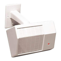
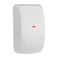
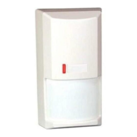
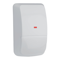
DS794Z Long Range Passive Infrared
Intrusion Detector with Self-test
Trademark names are used throughout this document. In most cases,
these designations are claimed as trademarks or registered trademarks in
one or more countries by their respective owners. Rather than placing a
trademark symbol in every occurrence of a trademark name, Bosch
Security Systems, Inc. (hereinafter referred to as Bosch) uses the
names only in an editorial fashion and to the benefit of the trademark
owner with no intention of infringing the trademark.
1.0 General Description
The DS794Z is a high performance intrusion detector designed to
provide an alarm condition upon the detection of an intruder moving
into or through its coverage pattern.
Technology designed into the DS794Z is based on the transmission
of infrared energy; all objects transmit infrared energy. The warmer an
object is, the more infrared energy transmitted. The DS794Z detects
the change in infrared energy that occurs when a target passes
through its view.
The coverage pattern, consisting of sensor fingers (to detect the
target) is arranged in a side-by-side array. The total number of fingers
is determined by the optical module used. The fingers are grouped
by polarity into pairs, with each pair consisting of one zone.
To detect motion, the DS794Z must first see a change in infrared
energy in one finger followed by a change of energy in the remaining
finger. Therefore, disturbances that occur in only one finger do not
constitute motion and are ignored.
The “catch sensitivity” may be changed by the installer to provide a
degree of sensitivity determined by each installation.
2.0 Specifications
• Coverage:
The DS794Z is shipped with the OA80 80 foot (24.4 m) Mirror installed.
If a 200 foot (61 m) range is desired, it will be necessary to install the
OA200 Mirror that is sent along with the unit.
Standard Range:
Broad (OA80 Mirror): 80 ft. by 50 ft. (24.4 m by 15.3 m)
Long (OA200 Mirror): 200 ft. by 10 ft. (61.0 m by 3.1 m)
Optional Range:
Long (OA120 Mirror): 120 ft. by 25 ft. (36.6 m by 7.6 m)
• Input Power: 6.0 to 15.0 VDC; 18 mA at 12 VDC.
• Standby Power: There is no internal standby battery. Connect to
DC power sources capable of supplying standby power if primary
power fails. Eighteen mA-H required for each hour of standby time
needed. Four hours (72 mA-H minimum) are required for UL Listed
Requirements.
• Sensitivity: Field selectable for Standard, Intermediate, or High.
• Alarm Relay: Silent operating Form “C” relay. Contacts rated 125
mA, 28 VDC maximum for DC resistive loads. Do not use with
capacitive or inductive loads.
• Tamper: Normally Closed (with cover in place) tamper switch.
Contacts rated at 28 VDC, 125 mA maximum.
• Trouble Output: A solid state open collector shorts to ground (-)
when the detector is in a trouble condition. Maximum current load
is 25 mA.
• Temperature: The storage and operating range is -20° to +120°F
(-29° to +49°C). For UL Listed Requirements, the range is +32° to
+120°F (0° to +49°C).
• Sonalert
Connector: Using a Sonalert type sounder (low voltage)
will provide an audible tone when the unit is in alarm. A sounder is
intended only as an aid for walk testing during installation.
• Reading Bosch Security Systems, Inc. Product Date Codes
For Product Date Code information, refer to the Bosch Security
Systems, Inc. Web site at: http://www.boschsecurity.com/datecodes/
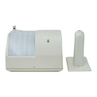
Front view with cover off
TERMINAL
STRIP
SETUP SWITCH BANK
(UNDER MIRROR ASSEMBLY)
SONALERT™ CONNECTOR
(UNDER MIRROR ASSEMBLY)
COVER TAMPER SWITCH
CIRCUIT BOARD RETAINER TAB (2)
WALK TEST/ALARM
LED INDICATOR
8
7
6
5
4
REPLACEABLE
OPTICAL MODULE
PERMANENT
RELFECTING MIRROR
BACKGROUND NOISE
VOLTAGE CONNECTOR
TAMPER RELAY
TO REPLACE OPTICAL MODULE,
LIFT THIS EDGE UP
REAR WIRE
ENTRANCE
REAR WIRE
ENTRANCE
SURFACE WIRE
ENTRANCE
BRACKET WIRE ENTRANCE
CORNER MOUNT
HOLES (4)
SURFACE MOUNT
HOLES (4)
COVER TABS (4)
TAMPER SCREW
HOLE
TEST/SOUNDER
CORD SLOT
Base
• Options: OA120-2* Mirror and TC6000 Test Cord.
* Shipped in packages of 2.
3.0 Mounting
Select a location likely to intercept an intruder moving across the
coverage pattern (review patterns on page 4). The recommended
mounting height is 7.5 ft. (2.3 m) for the DS794Z with the OA80 or
OA120 Mirror, or 10 ft. (3.1 m) for the OA200 Mirror. Each mounting
surface should be solid and vibration free. When mounting, avoid hot
and cold drafts, heat sources, animals and pets and direct sunlight.
Do not mount outdoors.
• Remove the cover by inserting a thin screwdriver into each of the four
slots on the cover. Twist gently until the cover snaps free of the tabs
on the base.