Installation Instructions
for the DS835i/DS835iT Series TriTech Microwave/PIR Intrusion Detectors with Pet Immunity
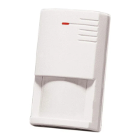
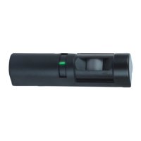
1.0 Description
The DS835i and DS835iT Series are high performance TriTech passive infrared (PIR)/microwave (MW) motion detectors that use advanced signal processing
to provide outstanding catch performance and unsurpassed false alarm immunity. They are designed to detect movement of a human body in the interior of a
structure as it moves across the detector's field of view. When motion is detected, the DS835i and DS835iT send an alarm signal to the control panel. With the
Pet Friendly
pet immunity, these detectors will not detect a dog up to 100 lbs (45 k) or two 60-lb (26 k) dogs, up to 10 cats, numerous rodents, or flying birds.
This pet immunity feature has not been tested by Underwriters Laboratories, Inc. (UL).
3.0 Installation
3.1 Remove the cover using a small
flat-blade screwdriver.
3.2 Press the vertical adjust tab
toward the side of the base and lift out
the board.
3.3 Select a mounting location.
Mount the sensor where an intruder will most
likely cross through the coverage pattern.
Note: The upper areas are not pet
immune.
3.5 Observe the Pet Immunity mounting restrictions.
Pet
Immune
Area
NO
OK
LED ON
7.5-9ft
7.5-9ft
• Input Power: 6 VDC to 15 VDC, 16 mA standby (up to 35 mA during
walk testing and alarm). Only use a limited power
source up to 5 A maximum.
• Standby Power: No internal standby battery. For UL Certificated
installations, the control unit or a Listed burglary
power supply must provide 4 hrs (64 mAh) standby
power.
• Alarm Relay: Silent operating Normally Closed reed relay. Contacts
rated 3 W, 125 mA, 28 VDC maximum for DC resistive
loads; protected by a 4.7 Ω, 1/2 W resistor in the
common “C” leg of the relay. Do not use with capacitive
or inductive loads.
• Temperature: Storage and operating temperature range is -40°F to
+120°F (-40°C to +49°C). For UL Certificated
installations, the temperature range is +32°F to +120°F
(0°C to +49°C).
• Microwave Frequency:
DS835i/835iT: 10.525 GHz (UL Listed)
DS835iTA: 10.687 GHz (Export only, not UL Listed)
DS835iTB: 9.9 GHz (Export only, not UL Listed)
• Coverage: 35 ft by 35 f. (10.7 m by 10.7 m)
• Tamper: ("T" models only) Normally Closed (with cover on). Contacts
rated at 28 VDC, 125 mA max. Connect tamper circuit to a
24-hour protection circuit.
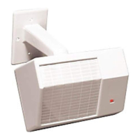
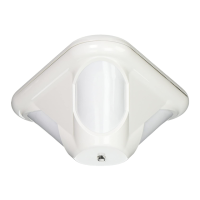
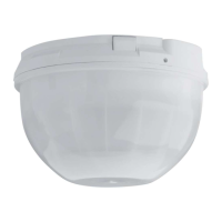
• Options: B335 Low Profile Swivel Mount Bracket, B338 Ceiling
Mount Bracket. (Using brackets is not recommended for pet
applications and might reduce range and increase dead zone
areas).
• Reading Bosch Security Systems, Inc. Product Date Codes
For Product Date Code information, refer to the Bosch Security Systems,
Inc. Web site at: http://www.boschsecurity.com/datecodes/
Bottom of Detector
Insert screwdriver here or here
Optional anti-tamper
screws at each end
3.4 Avoid:
Don't point where pets can climb.
7.5 - 9 ft.
(2.3 - 2.7 m)
Mount the detector 7.5 - 9 feet
(2.3 - 2.7 meters) above the floor
2.0 Specifications
Moving Objects
Heat
Sources
Windows
and
Uninsulated
Walls
Direct Hot or
Cold
Drafts
Mounting
Outdoors
Direct Sunlight
Air
Conditioning
Outlets