EasyManua.ls Logo

Bosch DS940 User Manual

Bosch DS940
2 pages
To Next Page IconTo Next Page
Page #1 background imageLoading...
Page #1 background image
DS940/DS940T
Passive Infrared Detector
Installation Instructions
1.0 Description
The DS940 is a high performance Passive Infrared (PIR) Motion Sensor which uses advanced signal processing to provide outstanding
catch performance and unsurpassed false alarm immunity. It is designed to detect movement in the interior of a structure by sensing the
Infrared energy emitted from the human body as it moves across the sensor’s field of view. When motion is detected the unit sends an alarm
signal to the control panel.
2.0 Specifications
Input Power: 9-15 volts DC
Current Draw: 17 mA @ 12 VDC (standby and maximum)
Standby Power: No internal standby battery. For UL Listed Prod-
uct Installations, 4 hours (68 mAh) standby
power must be provided by the control unit or
by a Listed burglary power supply.
Relay Form “A” Normally Closed (NC) contact set
rated for 125 mA@ 28 volts maximum DC, 18
volts maximum AC for resistive loads.
Tamper: (DS940T only) Normally Closed (with cover on).
Contacts rated at 28 VDC, 125 mA max. Con-
nect tamper circuit to a 24hr. protection circuit.
Temperature: -20° to +120°F (-29° to +49°C).
For UL Listed installations, the temperature
range is +32°F to +120°F (0°C to +49°C).
Humidity: 0 - 85% non-condensing.
Dimensions: 3 in. x 2.25 in. x 1.5 in. (HxWxD)
(7.6 cm x 5.7 cm x 3.8 cm)
Options: B335 Swivel Mounting Bracket. Use of this
bracket may decrease the PIR range and in-
crease dead zones.
Reading Bosch Security Systems, Inc. Product Date Codes
For Product Date Code information, refer to the Bosch Security
Systems, Inc. Web site at: http://www.boschsecurity.com/
datecodes/
.
3.0 Installation
3.1 Remove the cover using a
small flat-blade screwdriver.
3.2 Press the vertical adjust
tab toward the side of the
case and lift out the board.
3.3.
3.3.
3.4 Avoid.
3.3 Select a mounting location.
Mount the sensor where an
intruder will most likely cross
through the coverage pattern.
Bottom of Detector
Insert screwdriver here or here
LED
ON
7.5-9ft
3.3.
3.3.
3.5 Position the detector at the correct height.
7.5 - 9 ft.
(2.25 - 2.7 m)
Mount the detector 7.5 - 9 feet
(2.25 - 2.7 meters) above the floor
Moving Objects
Pets
Heat
Sources
Windows
and
Uninsulated
Walls
Air
Conditioning
Outlets
Direct Hot or
Cold
Drafts
Mounting
Outdoors
Direct Sunlight
Question and Answer IconNeed help?

Do you have a question about the Bosch DS940 and is the answer not in the manual?

Bosch DS940 Specifications

General IconGeneral
Coverage360°
Detection Range40 ft (12 m)
Temperature Range-10 to +50 °C
Relative Humidity0 to 93% non-condensing
TechnologyPassive Infrared

Summary

Detector Description

Detector Specifications

Operating Temperature Range

Specifies the operational temperature range for the detector, including UL listed requirements.

Input Power Requirements

Details the required input voltage and current draw for the motion sensor.

Standby Power Requirements

Outlines standby power needs for UL Listed Product Installations, requiring external power.

Relay Contact Specifications

Describes the Form "A" Normally Closed relay contact ratings for the detector.

Tamper Switch Specifications

Details the tamper switch specifications (NC, voltage/current ratings) for the DS940T model.

Operating Humidity Range

Specifies the acceptable non-condensing humidity range for proper detector operation.

Detector Dimensions

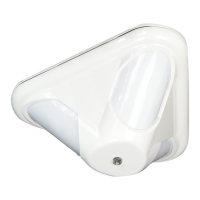
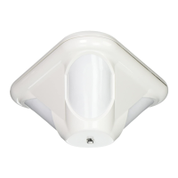
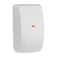
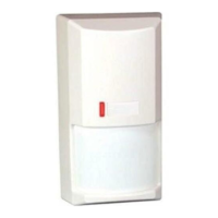
Provides the physical dimensions (Height, Width, Depth) of the PIR motion sensor.

Optional Mounting Bracket

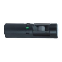
Mentions the B335 Swivel Mounting Bracket and its potential impact on PIR range.

Installation Procedures

Cover Removal

Instructions on how to remove the detector cover using a small flat-blade screwdriver.

Board Removal and Vertical Adjust

Describes how to lift out the circuit board and adjust the vertical tab for mounting.

Mounting Location Selection

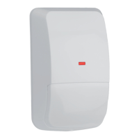
Guidance on selecting the optimal mounting location to maximize intruder detection.

Installation Avoidance Guidelines

Lists environmental factors and conditions to avoid during installation for reliable performance.

Detector Mounting Height

Specifies the recommended mounting height for the detector to achieve optimal coverage.

Mounting the Detector Unit

Instructions on mounting the detector unit using appropriate holes and hardware.

Installing the Board into the Case

Details on how to correctly install the circuit board into the detector housing.

Wiring the Detector

Step-by-step instructions for wiring the detector, including alarm and tamper contacts.

LED Operation Selection

Explains how to select the desired operation mode for the detector's LED indicator.

Look-Down Mask Adjustment

Instructions on how to peel away the look-down mask to adjust the detection pattern.

Walk Testing the Detector

Walk Test Warm-up Period

Important note about the detector's warm-up period before performing walk tests.

Coverage Patterns

Lens Masking

Guidance on masking specific areas of the lens diagram to adjust detection zones.
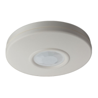
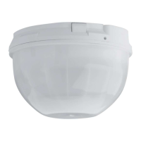
Related product manuals