2/11
DDS940/DS940T Installation Instructions
P/N: F01U035117-08 Page 2
© 2011 Bosch Security Systems, Inc.
130 Perinton Parkway, Fairport, New York 14450
www.boschsecurity.com
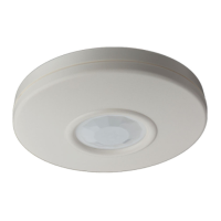
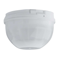
3.10 If look-down is desired, peel away the look-down
mask. Do not remove the clear plastic lens.
5.0 Coverage Patterns
3.9 Select LED Operation
3.8 Wire the Detector.3.7 Install the board into the case.
Be sure the vertical adjust tab
aligns with the correct mounting
height.
4.0 Walk test the detector. This test should
be performed at the time of installation and
annually thereafter.
This detector contains an environmental
stabilization circuit which requires
approximately 2 minutes after initial
power-up to warm up. During this time
the detector will not respond to any
movement.
Please wait 2 minutes after initial power-
up to perform any walk tests.
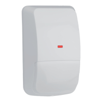
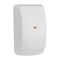
3.6 Mount the unit, using the appropriate
mounting holes.
LED
ON
7.5-9ft
7.5-9ft
OFF
ON
LED
ON
7.5-9ft
ON
Peel away
the mask
LED
ON
7.5-9ft
LED
ON
+
-
9-15
VDC
Alarm
Contacts
Tamper
Contacts
N
ormally
C
losed (NC) contacts
(DS940T
only)
Note:To avoid possible
circuit board
damage, use
only the
mounting
hardware
provided in the
appropriate
punch-out
mounting holes.
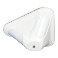
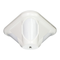
Corner Mount
Surface
Mount
Thinwall knockouts
for wiring
Don't overtighten the mounting screws
Cover may not attach correctly
Remove
Areas
if using the
B335 Bracket
Although generally not required, if
masking is desired, the lens diagram
shows the appropriate areas to be
masked (see shaded area on the
DS940 lens diagram). Use an
opaque material (such as, electrical
tape) to mask the desired areas.
1 234567891011
12 22
23 33
34 44
45 55
56 66
67 77
DS940 Lens
(inside view)
0
40
10
20
20
10
0
10
20
30
0
0
12
6
6
Meters
Feet
1
2
3
4
5
6
7
8
9
10
11
40
30
2010
0
0
0
10
12
3
0
7.5
Feet
Meters
Look
Down
67-
77
56-
66
45-
55
34-
44
23-
33
12-
22
1-
11