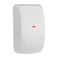
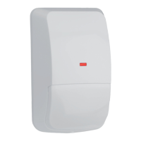
Installation Instructions
for the DS778
ASIC-Based
Passive Infrared Intrusion Detector
1.0 Specifications
• Input Power: 6.0 VDC to 15.0 VDC; 18 mA @ 12.0 VDC
• Standby Power: There is no internal standby battery.
Connect to DC power sources capable of
supplying standby power if primary power
fails. For each hour of standby time
needed, 18 mAh are required.
For UL
Certificated Installations, A minimum of
4 hours (72 mAh) is required.
• Coverage: 200 ft. by 15 ft. (60 m by 4.5 m)
• Sensitivity: Adjustable for Intermediate or High.
• Alarm Relay: Form “C” reed relay with contacts rated at
28 VDC, 125 mA max. for DC resistive
loads.
• Tamper Switch: Normally Closed (with cover in place)
tamper switch. Contacts rated at 28 VDC,
125 mA max.
• Temperature: The storage and operating range is -40°F
to +120°F (-40°C to +49°C).
For UL
Certificated installations, the temperature
range is +32°F to +120°F (0°C to +49°C).
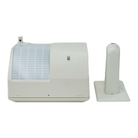
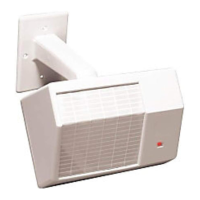
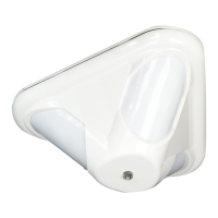
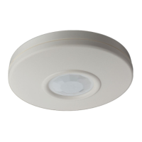
• Options: B328 Gimbal Mount Bracket, B335 Low
Profile Mount Bracket, B338 Ceiling Mount
Bracket, TC6000 Test Cord.
Note: Misalignment of the detector when using an optional
mounting bracket may reduce range.
2.0 Mounting
2.1 Mounting Considerations
• Select a location that is most likely to intercept an intruder moving
across the coverage pattern. The recommended mounting height
range is 6.5 ft. to 8.5 ft. (2 m to 2.6 m).
* The mounting surface should be solid and vibration free.
• Avoid direct hot and/or cold drafts, direct sunlight, heat sources,
windows, air conditioning outlets, and small animals.
• This detector won’t detect through glass.
• See
Section 8.0 Coverage Patterns
.
2.2 Surface or Corner Mounting
Note: For bracket mounting, refer to the installations supplied
with the bracket.
• Remove the cover. Insert a thin flathead screwdriver into the
notch at the bottom of the cover and pry up.
• Remove the chassis screw in the upper right corner of the
assembly (see
Figure A
). To remove the circuit board/mirror unit
from the enclosure, push the circuit board/mirror unit toward the
top of the enclosure until it clears its four retainer tabs, then lift
out.
• Open two holes (see
Figure A
) for surface or corner mounting.
Corner
Mounting
Holes (4)
Surface Mounting Holes
or Single Gang
Box Holes (2)
Bracket
Mounting
Hole
Wiring Knockouts
+2
0
-8
-16
+2
0
-8
-16
Noise
Voltage
12
3
Tamper Switch
LED
Configuration
Switches
T-Strip
Chassis
Screw
OPEN
-+
NO NCCTT
Figure A - Location of Major Items -
Circuit Board and Detector Enclosure
• Mark the location for the mounting screws. Use the enclosure
as a template. Pre-start the mounting screws.
• Open the appropriate wiring knockout and route the wiring
through (see
Section 3.0 Wiring
).
• Securely attach the detector.
• Replace the circuit board/mirror unit.
• Adjust the mirror.
Note: Excessive handling of the mirror surfaces may lead to
performance degradation.
- Adjust vertically from +2° to -18° by sliding the mirror forward
or back. See
Figures B
and
C
to set the correct Vertical Angle
based on the mounting height and desired range.
Mounting Height [ft. (m)]
6.5 (2)
7.5 (2.3)
8.5 (2.6)
Vertical Angle Setting
-1°
-2°
-2°
200 ft. (60 m)
100 ft. (30 m)
-2°
-2°
-3°
Figure B - Mounting Height/Range Chart
- The angle adjust markings are on the sides of the mirror
(see
Figure C
).
-16
-8
0
+2
Mirror
+2
0
-8
-16
+2
0
-8
-16
Set
at
-1°
Figure C - Setting Vertical Angle
- Slide the mirror forward or back until the angle hash marks
are in-line with the markers on each side of the frame.