EasyManua.ls Logo

Bosch DS720I User Manual

Bosch DS720I
6 pages
To Next Page IconTo Next Page
Page #1 background imageLoading...
Page #1 background image
© 2004 Bosch Security Systems
43744G
Page 1 of 6
2
3
4
DS720i Long Range
MIN
MAX
PIR
NV
MW
NV
AM
MW
1
2
3
4
5
6
7
8
9
10
1
2
3
4
5
6
7
8
2-1
2-2
2-4
2-5
2-3
2-62-72-82-9
2-10
3-1
3-2
3-3
3-4
3-5
3-6
feet
A
B
E
F
DGH
I
C
0 m
ft
20
10
0
10
20
6
3
0
3
6
0 120
I
G
H
D
E
F
A
B
C
20 40 60 80 100
ft
10
7.5
0
0 m
0
36
3
0
120
A - C
D - F
G - H
I
20 40 60 80 100
A
B
C
D
E
ft
0 m
0
7.5
0.0
7.5
300
2,3
2,3
91.4
50 100 150 200
A
B
D
E
C
250
ft
0 m
0
76
300
3,1
0
10
0
A
B
C
D
E
50 100 150 200 250
A
BCDE
GH
FIJ
K
ft
0 m
0
10
0
27
90
3
0
A - E
F - H
I, J
K
705030
7.5
m
ft
I
F
K
A
B
C
D
G
H
J
E
0 m
30
30
30
10
10
0
0
0
27
3
3
50
70 90
9
ft
9
m
ft
m
ft
m
ft
m
ft
m
ft
4-1
4-2
4-3
4-4
4-5
4-6
5
5-1
5-2
5-11
5-12
5-12
5-12
5-13
5-14
5-15
5-16
5-17
5-18
5-18
5-18
5-19
5-20
5-21
5-22
5-23
5-24
5-25
5-26
5-27
5-28
DS720i Long Range TriTech Detectors Installation Instructions ................................................................................. Page 3
DS720i Long Range Instrucciones de instalación del detector de intrusión por infrarrojos pasivos/microondas de
largo alcance dual DS720i .................................................................................................................Página 4
DS720i Long Range '6L䭓ᔶ㽚Ⲫঠӊ㹿ࡼ㑶໪㒓᥶⌟఼ᖂ⊶ܹ։᥶⌟఼ᅝ㺙䇈ᯢ ...........................................㄀义
Question and Answer IconNeed help?

Do you have a question about the Bosch DS720I and is the answer not in the manual?

Bosch DS720I Specifications

General IconGeneral
BrandBosch
ModelDS720I
CategorySecurity Sensors
LanguageEnglish

Summary

DS720i Long Range Installation Overview

System Components and Diagrams

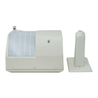
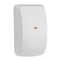
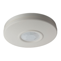
Visual representation of system parts and their layout, including numbered diagrams.

Coverage Pattern Diagrams

Illustrations showing PIR and microwave detection coverage areas at different ranges and heights.

Mounting and Installation Visuals

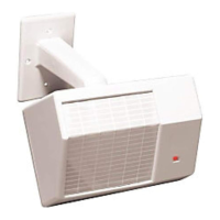
Step-by-step graphical guidance for installing the detector and its components.

Installation Procedures and Configuration

Bracket and Mirror Installation

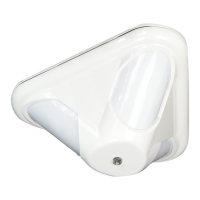
Details on installing mounting brackets and selecting/installing different mirrors.

Wiring and Terminal Connections

Schematic and explanation of terminal connections for power, relays, and tamper.

Memory and Feature Settings

Configuration of memory function and feature selection via DIP switches.

Walk Test

Procedure for conducting a walk test to verify functionality and coverage.

Specifications, Precautions, and Layout

Technical Specifications

Input power, relay ratings, temperature, microwave frequency, and dimensions.

Installation Precautions and Safety

Essential warnings and safety guidelines for device installation and placement.

Layout and Component Identification

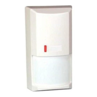
Identification of internal components and system layout for reference.

Advanced Features and Testing

Memory Operation Modes

Details on day mode, night mode, and reset for alarm memory function.

LED Status Indicators

Explanation of LED behavior for different events, faults, and operational states.

DIP Switch Functionality

Configuration of sensitivity, LED operation, and tamper settings using DIP switches.

Walk Test and Coverage Adjustment

Steps for walk testing and adjusting microwave sensitivity for optimal coverage.

Related product manuals