DS150i/DS151i Installation Guide Request-to-Exit PIR Detectors
1.0 Description
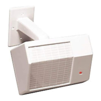
The DS150i is a passive-infrared detector designed for request to exit
(REX) applications. It is UL Listed as an access control device under the
UL 294 standard and is listed for Class I for UL Canada (ULC-S319). For
C-UL listed installation applications, the REX shall be connected to ULC-
S319 listed compatible devices (i.e. control units, power supply and
locks). Intended for indoor use only.
The relay output consists of two Form "C" contacts that can be adjusted to
latch from approximately 0.5 sec to 64 sec. The latch time features two
modes of operation: resettable (R) and non-resettable (NR). The relay can
also be programmed to fail safe or fail secure during a power loss.
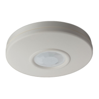
You can mount the DS150i on the ceiling or wall and aim and/or mask its
pattern for more effective use based on installation needs. The DS150i is
not designed as the primary means of exit for emergency egress
applications.
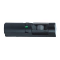
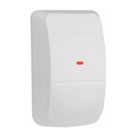
The DS150i is available in a light grey (DS150i) or a black (DS151i)
enclosure. An optional trimplate is also available in light grey (TP160) and
black (TP161).
2.0 Mounting
1. Select a mounting location over the center of the door or doors to be
covered. The target must walk directly toward the detector.
Mount the detector on the ceiling, wall, or door frame. The detector
can be surface mounted or mounted to a keyswitch plate with a "D"
size hole.
The DS150i is not tall enough to completely cover a single
gang box. Where aesthetics are important, mount it using
the optional trimplate (TP160 or TP161). Refer to Figure 1
for additional instructions for mounting with the trimplate.
Figure 1: Optional Trimplate
DOOR
DOOR
DS150i/DS151i
Optional Trimplate
(TP160/TP161)
Gang box
The arrows on the base indicate its correct mounting
orientation relative to the door.
The mounting height range is from 7 ft to 15 ft.
(2.1 m to 4.6 m) above the floor.
2. Remove the back cover from the detector. Insert the head of a small
straight edge screwdriver into the locking tab and pry the back cover
off.
When the back cover is removed, the front cover and
detector module separate.
3. Route the wiring as necessary through the wiring entrance (refer to
Figure 2). For surface wiring, use the break out wiring entrance on
the front cover (at the same end as the wire entrance).
4. Loosely mount the back cover to the mounting surface using the
supplied mounting screws.
5. Mount the detector module to the back cover. Aim the detector for
the desired coverage.
Coil excess wiring behind the back cover along the
channels provided.
Figure 2: Location of Major Items
-14° 4° 14°
-14° 4° 14°
ON DIP
Wall Mount
Angles
Wire
Plug
LED
Ceiling Mount
Angles
Wire
Entrance
DIP
Switches
3.0 Wiring
3.1 General Information
Only apply power after all connections are made and
inspected. Remove all system power (AC and standby
battery) before wiring the device.
Attach the wiring connector (provided) to the wire plug on the circuit board
(refer to Figure 3).
Figure 3: Connector to Plug Orientation (Default Switch Settings)
Refer to Figure 4 to wire the detector’s relay contacts.
Figure 4: Relay Contact Wiring