Installation Instructions
for the
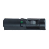
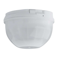
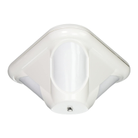
DS1103i Flush Mount
Glass Breakage Detector
1.0 Specifications
• Coverage: 25 ft. (7.6 m) maximum to farthest point of glass being
protected. For glass sizes over 12" by 12" (0.3 m by 0.3 m); types of
1/4" (0.64 cm) Plate, Tempered, Laminated, and Wired glass; and 1/8"
(0.32 cm) Plate glass (DSB).
• Mounting: Flush mount on the ceiling, on an opposite wall, or on an
adjacent wall.
• Input Power: 12 VDC (9 VDC min. to 15 VDC max.), 21 mA nominal
@ 12 VDC (26 mA max. in LED latch mode).
• Standby Power: Connect to power sources capable of supplying
standby power of 21 mA-H for each hour of required standby time.
Four hour minimum standby time required for U L Certificated
installations.
• Alarm Relay: Normally Closed reed relay (NC/C). Contacts rated
3.5 Watts, 125 mA @ 28 VDC for DC resistive loads. Protected by a
4.7 ohm resistor in the common “C” leg.
• Operating Temperature: -20° to +120°F (-29° to +49°C).
For U L
Certificated installations, the temperature range is +32° to +120°F
(0° to +49°C).
• Enclosure: 4.8” H, 3.25” W, 0.5” D (12 cm H, 8.3 cm W, 1.3 cm D).
When flush mounted: 4.8” H, 3.25” W, 0.25” D (12 cm H, 8.3 cm W,
0.625 cm D).
• Accessories: DS1110i Glass Breakage Tester.
2.0 Installation Considerations
NOTE: Always pre-test the detector’s location using the DS1110i
Glass Breakage Tester.
• Do Not…
…Mount the detector with obstructions between the glass being
protected and the detector.
…Mount on the same wall as the glass being protected.
…Mount the detector closer than 5 ft. (1.5 m) to the wall that
the glass being protected is on, or any hard, sound reflecting
surface.
…Mount closer than 2 ft. (0.6 m) to heating or cooling outlets;
mount as far away as possible. If drafts from these outlets
blow on the detector, select a different location for the
detector. Use the environmental test (see Section 4) to
verify good installation locations.
…Install on 24-hour protection circuits.
•
Remember…
…The best mounting location is 10 to 20 ft. (3 to 6 m) from the glass, in-
line with the glass’s center, and on the ceiling or opposite wall of the
glass being protected. Do not exceed maximum range.
…The detector should be within ±30° of the center of the glass to be
protected.
…Range will be reduced in areas that are acoustically soft. This may be
due to carpeting, drapes, plants, or other sound absorbing materials.
The DS1110i Glass Breakage Tester should be used to verify range in
all installations.
…Glass breakage detectors are intended only as perimeter protection
devices. They should always be backed up with motion sensors.
…Glass breakage detectors are designed to detect the breakage of
framed glass and may not detect such things as bullet holes,
spontaneous breakage of glass (with no impact), and removal of
glass.
• Maximum range:
The maximum detection range is 25 ft. (7.6 m) from the farthest
corner, for glass sizes 12" by 12" (0.3 m by 0.3 m) and larger.
Hint: Tie a 25 ft. (7.6 m) string to the detector. The string should be able to
touch every part of the glass being protected. If any part of the glass
can not be touched by the string, it is outside of the detector’s
coverage and additional detectors should be used.
3.0 Selecting a Mounting Location
Opposite Wall Mounting
• Mount the detector where there are
no objects between itself and the
glass.
•
Do not mount the detector closer
than 5 ft. (1.5 m) to the wall that the
glass being protected is on, or any
hard, sound reflecting surface.
• The detector should be within ±30°
of the center of the glass to be
protected (line B in Figure A).
• Make sure the detector is no farther than 25 ft. (7.6 m) from any corner
of the glass (line A in Figure A).
Ceiling Mounting
• The recommended location is half
the distance between the glass and
its opposite wall or 2/3 of the rated
range, whichever is smaller.
• Mount the detector where there are
no objects between itself and the
glass.
• Mounting to drop ceiling tiles is
acceptable.
•
Do not mount the detector closer than 5 ft. (1.5 m) to the wall that the
glass being protected is on, or any hard, sound reflecting surface.
• Make sure the detector is no farther than 25 ft. (7.6 m) from any corner
of the glass (line A in Figure B).
• The detector should be within ±30° of the center of the glass to be
protected (line B in Figure B).
Adjacent Wall Mounting (not preferred)
• Mount the detector where there are
no objects between itself and the
glass.
• Do not mount the detector closer than
5 ft. (1.5 m) to the wall that the glass
being protected is on, or any hard,
sound reflecting surface.
• Make sure the detector is no farther
than 25 ft. (7.6 m) from the farthest
corner of the glass (line A in Figure C).
Multiple Detectors
• In some installations, multiple
detectors must be used to protect
larger glass.
• As a general rule, if the glass is
wider than 20 ft. (6.1 m), multiple
detectors should be used.
• Place each detector in-line with the
center of each 20 ft. (6.1 m) section of glass.
• Space the detectors evenly across the glass, but no farther than 20 ft.
(6.1 m) apart (line B in Figure D).
• Do not mount the detector closer than 5 ft. (1.5 m) to the wall that the
glass being protected is on, or any hard, sound reflecting surface.
• Make sure each detector is no farther than 25 ft. (7.6 m) from any corner
of its 20 ft. (6.1 m) section (lines A in Figure D).
B
A
Figure A
B
A
Figure B
A
Figure C
A
A
Figure D
B