Page 2 © 2011 Bosch Security Systems, Inc. DS9360 Installation Guide
Note: The DS9360 base will not completely cover a 4-inch
square box. Where aesthetics are important, a 4-inch
octagonal box is recommended.
Hint: Mounting to removable ceiling tiles is not recommended
unless a sandwich is made of the base, ceiling tile, and a
back plate behind the tile. Covers used for 4-inch
octagonal and square boxes make a suitable back plate
(when used with bolts and wing nuts, as an example).
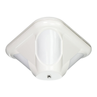
4.0 Selecting the Optical Module
• Replace the enclosure onto the base.
• For ceilings between 8 and 13 ft. (2.4 and 4.0 m) from the floor,
use the optical module marked AR8-13. This marking can be
found next to the two optical module tabs.
For ceilings between 13 and 18 ft. (4.0 and 5.5 m) high, use
the optical module marked AR13-18.
• To replace an optical module, push the optical module tabs
towards the center until the module snaps free of the circuit
board. Holding the new module by the tabs, snap the new
module into place.
NOTE: Avoid fingerprints on the mirrored surfaces. Should the
mirrored surfaces become soiled or otherwise marked,
they can be cleaned using a soft, clean cloth and any
commonly available, mild window cleaner.
5.0 Wiring
CAUTION
Only apply power after all connections have been
made and inspected. Do not coil excess wiring
inside detector.
NOTE: Input power must use only an Approved Limited Power
Source. Alarm and Tamper Contacts to be connected to a
SELV (Safety Extra-Low Voltage) circuit only.
-
+
NO
C
NC
T
T
ALARM
TAMPER
POWER
+
-
TR
• Terminals 1 (-) & 2 (+): Power limits are 6 to 15 VDC. Use no
smaller than #22 AWG (0.8 mm) wire pair between the unit and
the power source.
• Terminals 3 (NO), 4 (C), & 5 (NC): Alarm relay contacts rated
125 mA, 28 VDC maximum for DC resistive loads. Use
terminals 4 & 5 for Normally Closed circuits. Do not use with
capacitive or inductive loads.
• Terminals 6 (T) & 7 (T): Normally Closed tamper contacts
rated at 28 VDC, 125 mA.
• Terminal 8 (TR): Solid state Trouble output. Shorts to ground
(-) when the detector is in a Trouble condition.
6.0 LED Operation
The detector uses a tri-color LED to indicate the various alarm and
supervision trouble conditions that may exist. See chart below.
LED CAUSE
Steady red Unit alarm
Steady green + yellow + red Microwave activation (walk test)
Steady green PIR activation (walk test)
Flashing red Warm-up period after power-up
Flashing red (4 pulse sequence) Replace Unit
If the detector experiences a Microwave or PIR self-test failure, it is
in need of replacement.
NOTE: During walk testing, the LED will light for the first
technology (microwave or PIR) and then light red to
indicate a detector alarm. The LED will not indicate
activation of the second technology by lighting its color.
7.0 Feature Selection
LED
OFF ON
I H
Sensitivity
Jumper
I
H
OFF
ON
LED
Jumper
7.1 LED On/Off Pins
The ON position allows operation of the tri-color LED. If LED
indication is not desired after setup and walk tests are completed,
place in the OFF position. The OFF position does not prevent the
LED from indicating supervision trouble conditions.
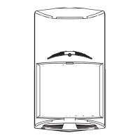
Mounting Base
REAR WIRE
ENTRANCE
WIRE
TIE-DOWNS (2)
TERMINAL
STRIP
INTERFACE
PINS
MOUNTING
SLOTS (4)
18
LED
OFF ON
I H
LED and
LED Jumper
Sensitivity
Jumper
Microwave
Adjustment
LED
Wires
To
Cover
Top View of Enclosure
MIN
Anti-vandal Screw Hole
Required for
EN50131
Installations
Anti-vandal Screw Hole
Required for
EN50131
Installations
 Loading...