Bosch Security Systems © 2003 Bosch Security Systems
130 Perinton Parkway, Fairport, New York, USA 14450-9199 DS939 Installation Instructions
Customer Service: (800) 289-0096; Technical Support: (888) 886-6189 P/N: 48782E 12/03
-
+
NO C
NC T T M
MAX
PIR Signal
Gain
12 ft.
(3.7 m)
20 ft.
(6.1 m)
35 ft.
(10.7 m)
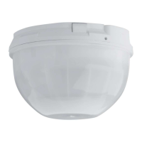
11.0 Optical Module Adjustment
• The PIR zones of the DS939 are divided into three groups. Each of these 3 groups can be independently adjusted vertically to provide the best
coverage within a room.
Only two coverage patterns are shown for clarity. PIR vertical adjustment knobs
• Use the following chart to adjust the optical modules based on the mounting height of the detector. The range shown is the distance from the detector
to the outside edge of the coverage pattern.
Mounting Height
Feet (Meters)
Maximum
Range
Feet (Meters)
8 (2.4) 10 (3) 12 (3.7) 14 (4.3) 15 (4.6) 16 (4.9) 18 (5.5) 20 (6.1) 22 (6.7) 24 (7.3) 25 (7.6)
10 (3) C A
15 (4.6) G D A A
20 (6.1) I G D B A A
25 (7.6) IFEDCAA
30 (9.1) HFEECBA
35 (10.7) IGGFECBAA
• In installations where a targeted coverage is required for part of the area, the optical modules must be adjusted for the correct coverage. In the
example below, the detector is mounted 12 ft. (3.7 m) above the floor. The distance to one wall is 20 ft. (6.1 m) and 35 ft. (10.7 m) to the opposite wall.
Using the chart above, the optical module for the 20 ft. (6.1 m) range was set to "D" and the optical module for the 35 ft. (10.7 m) was set to "I".
Only two coverage patterns are shown for clarity.