Electric Coolant Pump ECP 160 Installation | en 9
Bosch Engineering GmbH Installation Manual 11.04.2018 | V 1.0 |
3 Installation
The ECP 160 is designed for easy installation and fast swaps. To ensure a smooth run and a
long lifespan of the product the following requirements have to be met.
3.1 Installation Electronic
The electronics require supply air for certain loads and ambient temperatures. Minimum air
speed 5m/s to ensure safe operation.
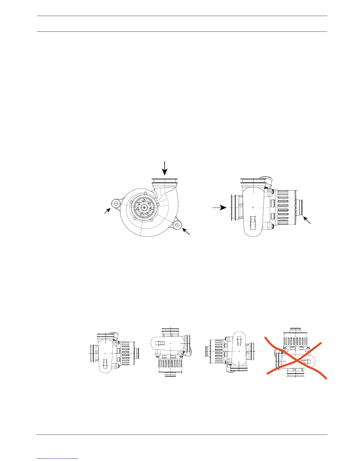
3.2 Installation Pump
– Mount the whole pump assembly rigidly. Rubber dampers may help to prevent long-term
damages caused by vibration.
– First, fix the pump, then the coolant and air connectors.
– Use two M5 screws (A) and the support on the motor side (B).
– The support (B) assists in absorbing the radial vibration stresses. The hole should have a
diameter of 23.5 mm.
– The water should drain and the place of installation should be chosen accordingly. The
cooling fins of the electronic must be protected against sludge and must not become
clogged. Don’t cover the cooling fins.
– An optimal air convection around the electrical motor and electronics, as well as the
cables, helps to guarantee smaller load currents and a longer life of the component.
– Mount the whole pump assembly either horizontally or vertically (referred to the
longitudinal axis of the motor).
– The suction nozzle must not be positioned downwards.
– If properly positioned, the pump will deaerate itself after short usage. Nevertheless, make
sure that no air can get into the pump element.
– The flanges of the coolant circuit quick couplings must not be subjected to tensile-
compression forces during operation.
– The pipe/hose connection must be mounted in such a way that the coupling connection
elements can take over the task of vibration decoupling.