2
EP Series
8733922168
Subject to change without prior notice Revised 12-13
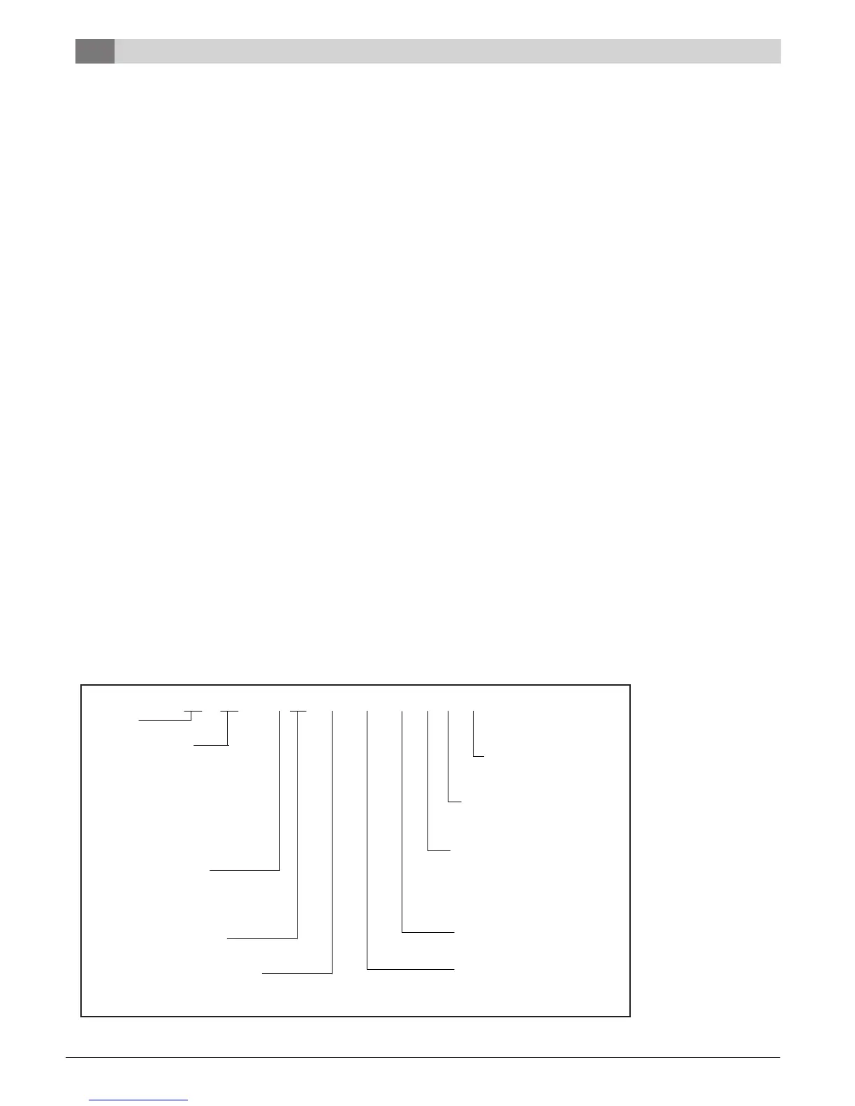
EP 048 - 1 VT C - F L T T B
SERIES
EP
NOMINAL CAPACITY
SUPPLY AIR LOCATION
007
009
012
015
018
024
030
036
042
048
060
070
VT
T = TO P
VOLTAGE DESIGNATION
HZ
0 – 115/1/6 0
S = STRAIGHT THRU
1 – 208-230 /1/6 0
E = END B LOW
2 – 277/1/60
3 – 208-230 /3/6 0
RETURN AIR LOCATION
4 – 460/3/6 0
L = LEFT
R = RIG H T
CABINET CONFI GURAT
IO
N
WATER CONECTIONS
VT – VE RTIC AL
LOC
ATIO N
HZ – HOR IZONTAL
F = FRONT
WATER TO REFRIG
ERANT HEAT EX
C –
COPP ER
N - CUPRONICKEL
MOTOR
T - ECM CONSTANT TORQUE
A - ECM CONSTANT CFM
REVISION
MODEL NOMENCLATURE
Table of Contents
©Copyright 2011 Bosch, Inc All rights reserved
TABLE OF CONTENTS
Model Nomenclature ...........................................................................................2
Initial Inspection .................................................................................................3
General Description ............................................................................................ 3
Moving and Storage ............................................................................................3
Safety Considerations .........................................................................................3
Location .............................................................................................................. 3
Installation .......................................................................................................... 4
Mounting Vertical Units ....................................................................................... 4
Mounting Horizontal Units ..................................................................................4
Condensate Drain ...............................................................................................5
Duct System ........................................................................................................5
Electrical ............................................................................................................. 6
Thermostat Connections ....................................................................................7
Safety Devices and the UPM Controller ...............................................................7
Sequence Of Operation ....................................................................................11
Unit Options Hot Gas Reheat ............................................................................11
Electric Heat .....................................................................................................15
Heat Recovery Package .....................................................................................16
Hot Gas Bypass ................................................................................................. 16
ECM Interface Board ......................................................................................... 16
Airow Selector ................................................................................................17
Dehumidication Method Selector ...................................................................17
Fluid Differential Pressure Switch ..................................................................... 18
Water Piping .....................................................................................................20
Well Water Systems ...........................................................................................20
Fresh Water Systems ......................................................................................... 21
Earth Coupled Systems .....................................................................................21
Unit Start-up .....................................................................................................21
Maintenance .....................................................................................................22
In-warranty Material Return ..............................................................................22
Unit Specications ............................................................................................ 24
Typical Wiring Diagrams ....................................................................................33
Unit Check-out Sheet ........................................................................................39
Troubleshooting ................................................................................................40