5
EP Series
8733922168
Revised 12-13 Subject to change without prior notice
connections, allowing easy removal of the access
panels, and replacement of air lters for routine
maintenance. This will ensure proper work space for
service personnel to perform maintenance or repair.
See Unit Specications for replacement lter sizes
in the back of this manual to ensure proper
clearances are provided during installation. Allow
adequate room below the unit for a condensate
drain trap on horizontal units.
Water freezes at 32°F. Frozen water coils are not
covered under the limited product warranty. It is
the installer’s responsibility to insure that the heat
pump unit is installed in a location or have taken
the proper precautions in order to prevent
rupturing the water coil due to freezing conditions.
The heat pump unit is designed for conditioned
space installation only. If the source water is
subjected to conditions where ambient
temperatures can fall below freezing, some form of
freeze protection should be employed. In an open
loop system this may entail running the water pump
continuously to prevent freezing. An antifreeze
solution wherever possible should be used if water
will be subject to freezing. Consult the factory in
these instances for guidance.
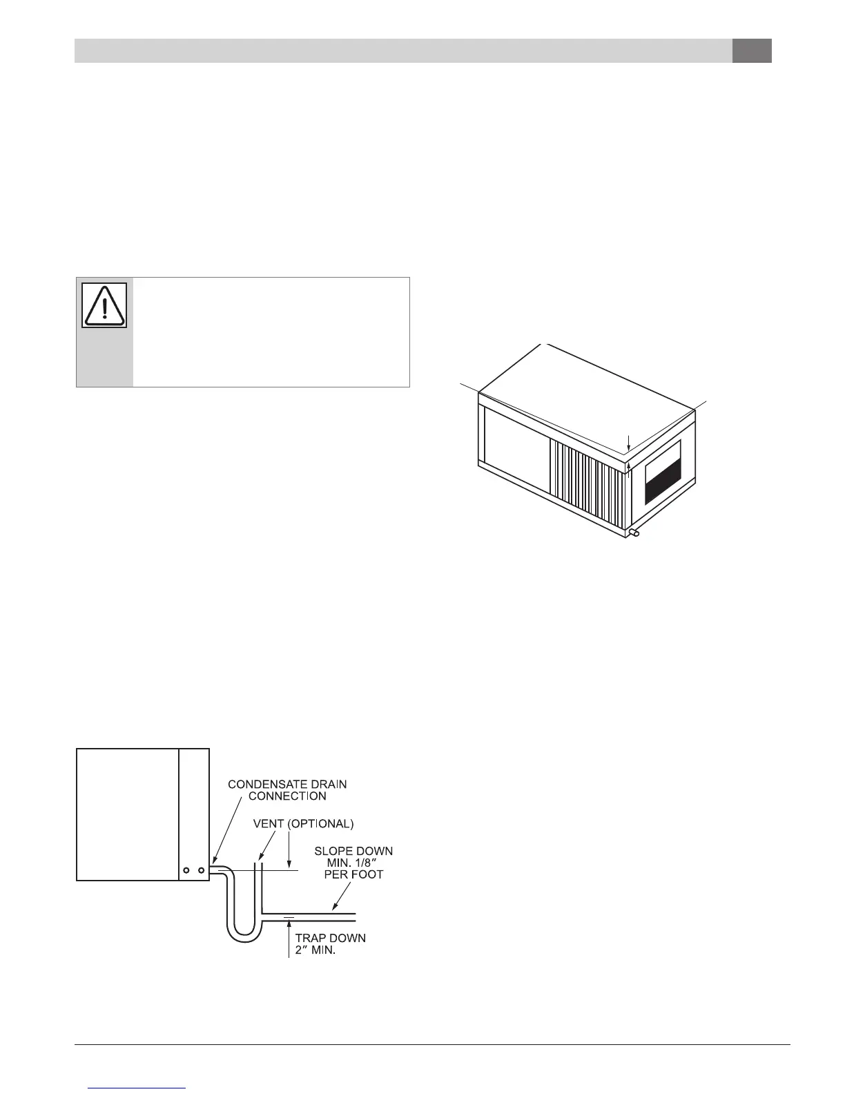
CONDENSATE DRAIN
A drain line must be connected to the heat pump
and pitched away from the unit a minimum of 1/8”
per foot to allow the condensate to ow away from
the unit.
Figure #3— Heat pump condensate trapping
This connection must be in conformance with local
plumbing codes. A trap must be installed in the
condensate line to insure free condensate ow.
(Heat Pumps are not internally trapped). A vertical
air vent is sometimes required to avoid air pockets
(See Figure #3). The length of the trap depends on
the amount of positive or negative pressure on the
drain pan. A second trap must not be included.
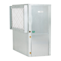
The horizontal unit should be pitched
approximately 1/4” towards the drain in both
directions, to facilitate condensate removal. See
Figure 4 below.
Figure #4 – Sloped horizontal unit installation
DUCT SYSTEM
A supply air outlet collar and return air duct ange
are provided on all units to facilitate duct
connections. See Unit Specications for duct collar
connection sizes in the back of this manual.
A exible connector is recommended for supply
and return air duct connections on metal duct
systems. All metal ducting should be insulated with
a minimum of one inch duct insulation to avoid heat
loss or gain and prevent condensate forming during
the cooling operation. Application of the unit to
uninsulated duct work is not recommended as the
unit’s performance will be adversely affected. Do
not connect ducts directly to the blower outlet;
factory supplied duct collars should be used for the
connection to minimize unit vibration and noise
transmission to the ductwork and ultimately into
the conditioned space. The factory provided air
lter must be removed when using a lter back
return air grill. The factory lter should be left in
place on a free return system.
ELEVATION LINE
WHEN MOUNTED LEVEL
1/4″
Condensate Drain