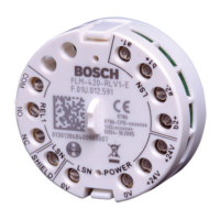
Product Description F L M - I 420- S
English
Bosch Sicherheitssysteme GmbHF.01U.003.287 | A3 | 2008.03 18 / 36
Functional Description
The short-circuit isolator isolates alarm zones in which a short circuit or an interruption due to wire
break or detector removal has occurred. This means the functionality of the remainder of the network
remains preserved.
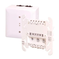
Wiring
Pos. Description Connection
1 b1+
2 a-
LSN
3 b2+
4 N/A
5 N/A
,
.
.
through ext. auxiliary voltage and for
6 N/A
shielding
Adress Setting
Mode/
XXX
X
XXXXX
CL 0 0
000
1...254
FPA-
5000
BZ 500 LSN
UEZ 2000 LSN
UGM 2020
255...299
_
_
_
D
D
D
D
B
Technical Specification
Address setting 0 0 0 Loop/stub in LSN improved mode with automatic addressing
(T-tap system not possible)
Address setting 1...254 Loop/stub/T-tap system in LSN improved mode with manual ad-
dressing
Address setting CL 0 0 Loop/stub in „classic“ LSN mode
Input voltage (min - max) 15 V DC - 33 V DC
Maximum current consumption
- during initialization
- following the initialization
(from LSN)
<0,4mA
<0,25mA
Safety class as per IEC 60950 III
Protection class as per IEC 60529 IP 54
Permitted operating temperature -20°C...50°C
Permitted storage temperature -25°C...85°C
Permitted relative humidity < 96%
Housing material and color PPO (Noryl), signal white (RAL 9003)
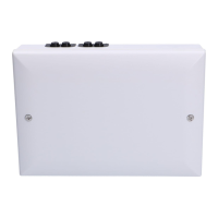
Material interface module housing
Material surface-mount housing
PPO (Noryl)
ABS + PC-Blend
563412
INFO
It is not permitted to use different adressing modes together.
 Loading...