18 en | Wiring MUX expansion module
2016.10 | 1.0 | F.01U.330.684
Bosch Security Systems. Inc.
Maximum wire length
* This table gives capacitance in microFarads (μF), but the
graph gives it in nanoFarads ( nF). For example, 0.12μF =
120nF.
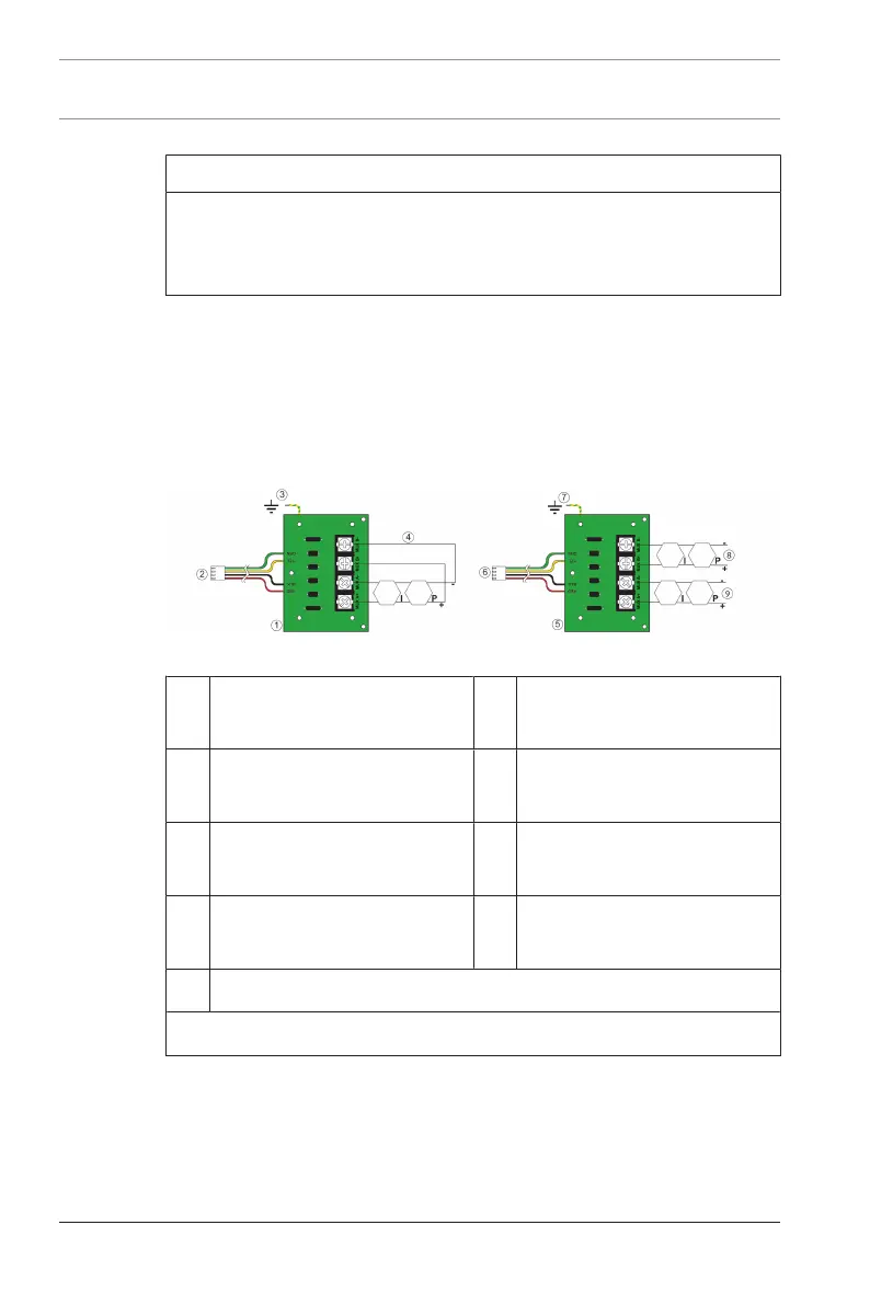
4.2 Wiring the loops
Determine the appropriate configuration (number and type of
devices and wire size and length).
1. Run solid wire from the FACP to the device locations and
connect the multiplex loop.
Figure4.1: Wiring Class A loops and Class B branches
1 I/O module wired as Class
A
2 Wiring harness
3 Ground wire 4 Class A loop (addresses 9
to 128)
5 I/O module wired as Class
B
6 Wiring harness
7 Ground wire 8 Class B branch
(addresses 129 to 255)
9 Class B branch (addresses 9 to 128)
All MUX terminals are power-limited and supervised
2. Ensure the loop is disconnected from the FPE‑7039
Module.
3. Measure loop resistance by shorting:
the end of the farthest device in ClassB.