WW
WW
W
ARNINARNIN
ARNINARNIN
ARNIN
GG
GG
G
LP & NLP & N
LP & NLP & N
LP & N
G ARE EXTREMELG ARE EXTREMEL
G ARE EXTREMELG ARE EXTREMEL
G ARE EXTREMEL
Y FLY FL
Y FLY FL
Y FL
AMMABLE SOAMMABLE SO
AMMABLE SOAMMABLE SO
AMMABLE SO
TT
TT
T
AKE EXTRA PRECAAKE EXTRA PRECA
AKE EXTRA PRECAAKE EXTRA PRECA
AKE EXTRA PRECA
UTIONS WHENUTIONS WHEN
UTIONS WHENUTIONS WHEN
UTIONS WHEN
PERFPERF
PERFPERF
PERF
ORMINORMIN
ORMINORMIN
ORMIN
G ANY WG ANY W
G ANY WG ANY W
G ANY W
ORK TORK T
ORK TORK T
ORK T
O THE HEAO THE HEA
O THE HEAO THE HEA
O THE HEA
TERTER
TERTER
TER
CT-28
page 1 of 1
rev 10/06
Bosch Water Heating
340 Mad River Park, Waitsfield, VT 05673
©BBT NORTH AMERICA CORPORATION
Bosch Group
REPLACING THERMOCOUPLE AND
FLUE SENSOR
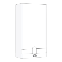
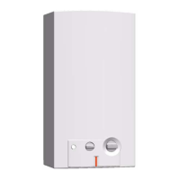
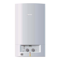
MODELS: 1000P, 1600P
260PN, 425PN
Tools needed:
Pliers, 8mm or adjustable wrench
Removing thermocouple and flue sensor
1. Turn off gas supply to the water heater.
2. Turn off water supply into the water heater using in-
staller supplied cold water isolation valve.
3. Remove front cover as per instructions in the installa-
tion manual.
4. The t hermocouple is located in the center of the burner
rows directly behind the white ceramic spark electrode.
Carefully, push down on the top on the thermocouple
with a flat head screw driver until it clicks out of
bracket. Pull down on thermocouple wires until it is
free from burner bracket. (Fig. 1).
5. Loosen and remove only the 8mm brass nut from elec-
tromagnet on rear of gas valve. (Fig. 2)
6. Disconnect wire from thermocouple at the lower tem-
perature limiter (ECO). (Fig. 2)
7. Disconnect wire from the flue gas sensor at the upper
temperature limiter (ECO). (Fig. 3)
8. Remove Philips head screw attaching the flue gas sen-
sor to the draft hood. (Fig. 3)
9. Remove thermocouple & flue gas sensor with wires
from heater.
Installing thermocouple and flue sensor
NN
NN
N
oo
oo
o
tt
tt
t
ee
ee
e: Replacement parts will come as two separate
parts. Attach the thermocouple to the safety circuit
wiring with the quick connect plug before proceeding.
1. Attach flue gas sensor to the upper right hand side of
the draft hood using Philips head screw. Flue gas sen-
sor should be on the inside of the draft hood in order
to proper ly sense flue gas spillage. (Fig. 3)
2. Connect wire connection at upper temperature limiter
(ECO). (Fig. 3)
3. Feed wires down the right hand side of the water heater
and secure in wire tie on the lower right side of heater
chassis. Make sure that none of the wires rest against
the copper heat exchanger.
4. Connect wire connection from thermocouple to lower
temperature limiter (ECO). (Fig. 2)
5. Feed replacement thermocouple from underneath burn-
ers into burner bracket. Push into bracket until it snaps
in place. (Fig. 1)
6. Thread 8mm nut end from flue sensor wire into elec-
tromagnet and tighten.
NN
NN
N
oo
oo
o
tt
tt
t
ee
ee
e:
Do noDo no
Do noDo no
Do no
t ot o
t ot o
t o
vv
vv
v
er tighter tight
er tighter tight
er tight
en.en.
en.en.
en.
7. Reinstall heater cover as per instructions in the ins tal-
lation manual.
8. Reopen water and gas supplies and return heater to
service.
Thermocouple location
FIGURE 1
Thermocouple
tip
(press down)
Electromagnet Location (view from bottom of heater)
FIGURE 2
8mm nut
Lead from
upper ECO
Lead from
thermocouple
Flue sensor Location (view from right side of heater)
FIGURE 3
Flue gas
sensor
Lead from flue
gas sensor
Lower
temperature
limiter
Upper
temperature
limiter
 Loading...