WW
WW
W
ARNINARNIN
ARNINARNIN
ARNIN
GG
GG
G
LP & NLP & N
LP & NLP & N
LP & N
G ARE EXTREMELG ARE EXTREMEL
G ARE EXTREMELG ARE EXTREMEL
G ARE EXTREMEL
Y FLY FL
Y FLY FL
Y FL
AMMABLE SOAMMABLE SO
AMMABLE SOAMMABLE SO
AMMABLE SO
TT
TT
T
AKE EXTRA PRECAAKE EXTRA PRECA
AKE EXTRA PRECAAKE EXTRA PRECA
AKE EXTRA PRECA
UTIONS WHENUTIONS WHEN
UTIONS WHENUTIONS WHEN
UTIONS WHEN
PERFPERF
PERFPERF
PERF
ORMINORMIN
ORMINORMIN
ORMIN
G ANY WG ANY W
G ANY WG ANY W
G ANY W
ORK TORK T
ORK TORK T
ORK T
O THE HEAO THE HEA
O THE HEAO THE HEA
O THE HEA
TERTER
TERTER
TER
CT-11
page 1 of 1
rev 10/06
Bosch Water Heating
340 Mad River Park, Waitsfield, VT 05673
©BBT NORTH AMERICA CORPORATION
Bosch Group
WINTERIZING FOR SEASONAL USE
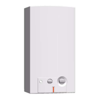
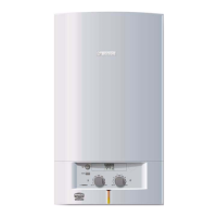
MODELS: 1000P, 1600P, 1600H
260PN, 425PN, 425HN
Please note that the instructions in the manual state that the water heater must not be installed in a location where
it may be exposed to freezing temperatures. If the heater must be left in a space which is likely to experience freezing
temperatures (less then 32º F), all water must be drained from the heater. Damage as a result of improper drainage
will not be covered under warranty.
Draining the heater
1. Shut off gas to heater.
2. Shut off water supply to the heater using installer sup-
plied cold water isolation valve. If none installed, in-
stall before proceeding.
3. Open lowest hot water faucet to drain lines and re-
lieve pressure in heater.
4. Position a bucket below water connections to water
heater.
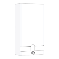
5. Remove the retaining clip (Fig. 1, Num. 1) from the
threaded bushing.
6. Remove the threaded bushing (Fig. 1, Num. 2) from
the water valve.
7. Contents of he ater and water lines will drain.
8. Removal of piping between the water valve and heat
exchanger may be necessary to ensure all water has
been drained (Fig. 1, Num. 3)
On Models 1000P, 1600P, 260PN, 425PN:
Remove retaining clips at water valve and heat ex-
changer connections.
On Models 1600H, 425HN:
Remove reatining clips at water valve and base of
hydrogenerator.
9. Remove piping and save for reinstalla tion when heater
is returned to service.
Note: If using the AQ4 powervent, all flow
switch piping should be disconnected and
drained.
FIGURE 1
 Loading...