WW
WW
W
ARNINARNIN
ARNINARNIN
ARNIN
GG
GG
G
LP & NLP & N
LP & NLP & N
LP & N
G ARE EXTREMELG ARE EXTREMEL
G ARE EXTREMELG ARE EXTREMEL
G ARE EXTREMEL
Y FLY FL
Y FLY FL
Y FL
AMMABLE SOAMMABLE SO
AMMABLE SOAMMABLE SO
AMMABLE SO
TT
TT
T
AKE EXTRA PRECAAKE EXTRA PRECA
AKE EXTRA PRECAAKE EXTRA PRECA
AKE EXTRA PRECA
UTIONS WHENUTIONS WHEN
UTIONS WHENUTIONS WHEN
UTIONS WHEN
PERFPERF
PERFPERF
PERF
ORMINORMIN
ORMINORMIN
ORMIN
G ANY WG ANY W
G ANY WG ANY W
G ANY W
ORK TORK T
ORK TORK T
ORK T
O THE HEAO THE HEA
O THE HEAO THE HEA
O THE HEA
TERTER
TERTER
TER
CT-04
page 1 of 1
rev 10/06
Bosch Water Heating
340 Mad River Park, Waitsfield, VT 05673
©BBT NORTH AMERICA CORPORATION
Bosch Group
CHECKING GAS PRESSURE
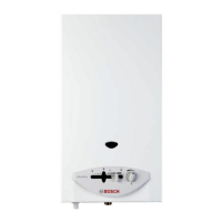
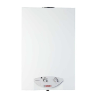
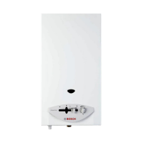
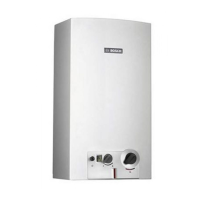
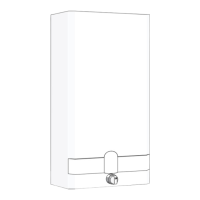
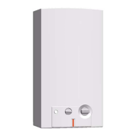
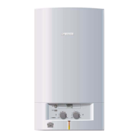
MODELS: 1000P, 1600P, 1600H
260PN, 425PN, 425HN
A. Connecting manometer:
1. Turn off gas using installer supplied manual shutoff.
2. Remove front cover (see manual for instructions) and lo-
cate inlet gas pressure tap above the regula tor on the gas
inlet pipe and the manifold gas pressure tap on the right
side directly belo w the burner (F ig. 1).
3. Select appropriate pressure tap per specific pressure test
(see steps B and C). Loosen the screw from test point fit-
ting (do not remove) and connect manometer tube on test
point.
B. Static pressure test (Inlet pressure tap
only)
1. Turn gas supply back on.
2. Operate all other gas appliances at maximum output.
3. Record static pressure reading in Table 1.
4. Leave manometer connected to inlet tap for oper ating pres-
sure test.
C. Operating pressure test
1. Light pilot if neccessary (1000P, 1600P, 260PN and 425PN
models).
2. All other gas appliances should still be running at full ca-
pacity.
3. Set heater to maximum output:
1000P, 1600P, 260PN, 425PN:
Set gas slide control to the right. Turn temperature
adjustment knob full clockwise.
1600H, 425HN:
Turn power adjustment knob full clockwise. Tur n
temperature adjustment knob full clockwise.
4. Open all hot water taps supplied by this unit.
5. Record inlet tap oper ating pressure reading in Table 1.
6. Turn off gas supply as well as all hot water taps. Disconnect
manometer from the inlet tap. Tighten screw in tap fitting
or gas leak may occur.
7. Reconnect manometer to the manifold gas pressure tap.
8. Tur n gas supply back on and follow steps 1 through 4.
9. Record manifold tap operating pressure reading in Table 1.
10. Tur n off gas supply as well as all hot water taps. Disconnect
manometer from the manif old tap. Tighten screw in tap fit-
ting or gas leak may occur.
11. Put cover back on water heater, open gas supply and return
heater to service.
TABLE 1
Static gas pressure: “ W.C.
Required static gas pressure (all models:
NG 7” - 14” W.C.
LPG 11” - 14” W.C.
Operating gas pressure:
Inlet Tap “ W.C.
Manifold tap “ W.C.
Minimum require operating gas pressure:
GAS PRESSURE TEST POINTS
Mainfold tap
Inlet tap
FIGURE 1
 Loading...