WW
WW
W
ARNINARNIN
ARNINARNIN
ARNIN
GG
GG
G
LP & NLP & N
LP & NLP & N
LP & N
G ARE EXTREMELG ARE EXTREMEL
G ARE EXTREMELG ARE EXTREMEL
G ARE EXTREMEL
Y FLY FL
Y FLY FL
Y FL
AMMABLE SOAMMABLE SO
AMMABLE SOAMMABLE SO
AMMABLE SO
TT
TT
T
AKE EXTRA PRECAAKE EXTRA PRECA
AKE EXTRA PRECAAKE EXTRA PRECA
AKE EXTRA PRECA
UTIONS WHENUTIONS WHEN
UTIONS WHENUTIONS WHEN
UTIONS WHEN
PERFPERF
PERFPERF
PERF
ORMINORMIN
ORMINORMIN
ORMIN
G ANY WG ANY W
G ANY WG ANY W
G ANY W
ORK TORK T
ORK TORK T
ORK T
O THE HEAO THE HEA
O THE HEAO THE HEA
O THE HEA
TERTER
TERTER
TER
CT-07
page 1 of 1
rev 10/06
Bosch Water Heating
340 Mad River Park, Waitsfield, VT 05673
©BBT NORTH AMERICA CORPORATION
Bosch Group
LOWERING TEMPERATURE
MODELS: 1000P, 1600P, 1600H
260PN, 425PN, 425HN
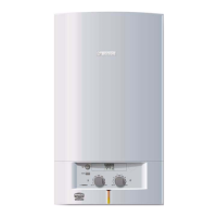
When the temperature adjustment knob on the front of
heater is turned all the way clockwise (hotter temps.),
the heater requires a 0.6 gallon per minute flow rate to
activate. When the temperature adjustment knob is turned
all the way counter-clockwise (cooler temps.), the unit
will require a 1.1 gallon per minute flow rate to activate.
Although common sense tells us to turn this knob counter-
clockwise to achieve a lower outlet temperature, we rec-
ommend that the temperature adjustment knob be kept
all the way clockwise, to take advantage of the 0.6 gpm
activation point. Please move knob to this setting and
follow the steps below for alternative ways of lowering
temper ature.
Solution:
Increased water flow helps to lower the outlet tempera-
ture and ensures that the heater stays activated espe-
cially when mixing cold water at the outlet.
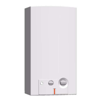
1. Increase the flow by cleaning the inlet filter screen in
the heater. (Fig. 1) Consult bulletin CT-12 Cleaning in-
let filter for more detailed instructions on removing
the inlet filter.
2. Increase the flow at all outlets. For sinks, remove fau-
cet aerator screen on end of sink. Flush screen with
water to clean and reinstall. For showers, remove
showerhead and flush with water. If the he ad is clogged
with mineral deposits, clean according to
manufacturer’s specifications or replace. Please note,
if the showerhead is a hand-held/wand style, these can
be extremely restrictive. If cleaning or flushing
showerheads/aerators fails to produce a dequate flow,
try upgrading with higher flowing versions.
3. Decrease the gas volume by moving gas slide control
(models 260PN, 425PN, 1000P, 1600P) or gas control
knob(models 425HN, 1600H) to the small flame
position.
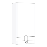
4. If temperatures are still too hot, increase water flow
by removing the water governor/restrictor. Shut off cold
water supply to heater and remove wire clip on volu-
metric water governor housing from right side of wa-
ter valve behind water outlet pipe. (Fig. 2) Remove
retaining cap with o-ring and spring/cylinder assem-
bly inside. (Fig. 3) Re-install retaining cap with lubri-
cated o-ring and wire clip only. No inner components
should be left inside. Operate heater with the flow
control turned all the way clockwise.
FIGURE 1
Removing Water Filter
FIGURE 3
Water Governor Location
Cylinder
FIGURE 2
Water Governor Location
Water governor
clip
Spring
Retaining
cap
 Loading...