8 716 473 071 (2015/04)HydroPower
Commissioning | 13
5.3 Inlet pressure adjustment
Gas pressure adjustment (commissioning) MUST be carried
out upon installation.
▶ Check the gas indicated on the rating plate and front cover
label is the same as the gas to which the heater is
connected.
▶ Loosen the pressure test point screw on the left hand side
of the gas valve (Fig. 10, [A]) and attach a manometer.
Static Pressures should be greater than or equal to the figures
in table 7.
Adjust the appliance regulator to achieve the figures in table 7
with the unit operating and all hot water taps open for full water
flow through the unit.
If the operating inlet pressure cannot be achieved there may be
an issue with the gas supply meter (NG), cylinder regulator
(LPG), or pipe sizing (Ref AS/NZS5601). This must be resolved
before proceeding.
▶ Remove manometer and tighten test point screw.
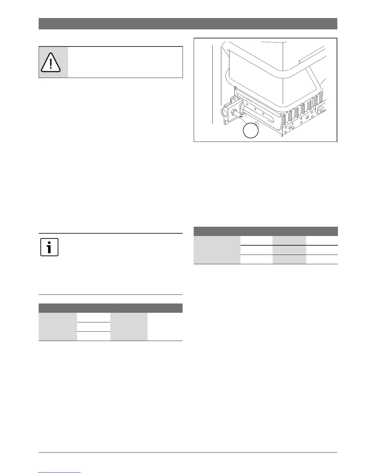
5.4 Burner pressure adjustment
▶ Loosen the burner test point captive screw ( Fig. 9 [D]).
▶ Connect a manometer to the burner pressure measuring
point.
Fig. 9 Burner pressure measurement point
Maximum gas flow adjustment
▶ Turn on the water heater with the gas control slide set to the
Right (maximum gas flow).
▶ Ensure the water control knob is fully open (anticlockwise).
▶ Adjust appliance regulator to the maximum burner
pressure figure on the rating plate (See table 8 below).
▶ Turn the water control knob fully clockwise and check that
the burner pressure does not exceed the maximum.
Minimum gas flow adjustment
▶ With the heater operating, move the gas selector to the Left
(minimum gas position).
▶ Ensure the water control knob is fully closed (clockwise).
▶ Open various hot water taps.
▶ Using the adjusting screw (Fig. 11, [B]) to adjust the gas
pressure to the values indicated in table 9.
▶ Close the hot water taps.
DANGER:
The following procedures must only be
performed by a qualified technician.
Measurements should be made with unit
operating with all hot water taps opened to
achieve maximum water flow through the
unit.
If possible all other gas appliances (ducted
heating etc.) should be operating at the same
time.
Natural gas LP gas
Inlet Pressure
(kPa)
TF250/10H
1.13 2.75TF325/13H
TF400/16H
Table 7 Inlet pressure
Natural gas LP gas
Max. Burner
Pressure (kPa)
TF250/10H
0.89 2.60
TF325/13H
0.84 2.60
TF400/16H
0.78 2.60
Table 8 Maximum burner pressure
 Loading...