Table 2.1:
Maximum detection range
NOTICE!
Manual mode is active for 20 minutes
after power up.
NOTICE!
Cycle the sensor power after
changing switch settings.
NOTICE!
Do not use double-sided tape or
RTV which reduces vibration.
5 | Adjust potentiometer
Fine tune the sensitivity level by turning
the potentiometer clockwise to increase
sensitivity or counter-clockwise to decrease
sensitivity. During Self-learning mode, adjust
the potentiometer until the sensor LED turns
off, indicating that the sensor is correctly
configured.
Figure 5.1: Sensitivity potentiometer
– +
4 | Switch settings
The switch settings change sensor
configuration or sensitivity.
Figure 4.1: Switches
Switches 1 and 2 - sensitivity level setting.
Refer to sections 6 and 7 for configuring
these switch settings during installation.
Switch
Sensitivity Level
1 2
OFF OFF Low (default - least
sensitive)
OFF ON Low-medium
ON OFF High-medium
ON ON High (most sensitive)
4.2 | Set pulse count
Switch 4 Drill/saw detection
ON Disabled
OFF Enabled (default)
Switch 4 - drilling or sawing detection
setting.
4.5 | Set installation mode
Switch 6 - Manual or Self-learning mode
setting.
Switch 6 Installation mode
ON Self-learning mode
OFF Manual mode (default)
LED Condition
Green flash Vibration, movement,
contact or attack attempt
or during configuration.
Red on 2 seconds Alarm
Red on steady Sensor fault, sensor
position changed from
original installation.
Switch 5 LED function
ON Enabled (default)
OFF Disabled
Switch 3 Pulse count
ON 4 pulses
OFF 1 pulse (default)
4.3 | Set drill/saw detection
Switch 3 - pulse count setting. The sensor
generates an alarm when noise occurs
within the pulse count. When set to ON
the alarm triggers on 4 pulses within 40
seconds (15 seconds - 10 seconds - 15
seconds). When set to OFF, the alarm
triggers on the first pulse.
4.4 | Set LED
Switch 5 - LED setting. Do not disable this
setting during installation.
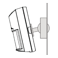
3 | Installation
Mounting the base:
1. Identify mounting location and surface.
2. Remove or drill through the mounting
holes in the base.
3. Insert the screws into the mounting
holes or use glue to secure the base to
the surface.
Figure 3.1: Unlocking and opening cover
1. Insert a slotted screwdriver into the
rotary lock on the front of the sensor
and turn counter-clockwise to the open
position (unlocked).
2. Pull apart the sensor from the top to
remove the cover from the base.
Figure 3.2: Screw locations
3.1 | Wiring
1. Insert the wire through the grommet
(removable). Refer to Figure 3.3.
2. Attach wire to the appropriate terminals.
Tamper and Alarm Contact normally-
closed (NC), Power 12VDC. Refer to Figure
3.4.
Figure 3.3: Wiring
Figure 3.4: Terminal
– Install the ISC-SK10 indoors and mount
on a variety of flat surfaces.
– Use the included screws or an adhesive
glue to secure the unit to the surface.
2 | Installation considerations
4.1 | Set sensitivity level
Surface Radius (m) Radius (ft)
Concrete 1.5 5
Brick wall 2.5 8
Steel 3 10
Wood 3.5 11.5
Glass 3.5 11.5
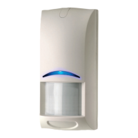
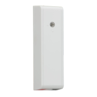
The ISC-SK10 is an advanced shock sensor
designed to monitor and detect mechanical
attacks.
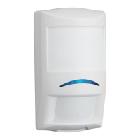
Callout ― Description
1 ― LED
2 ― Potentiometer (sensitivity adjustment)
3 ― Cover tamper
4 ― Terminal block
5 ― Switches
Figure 1.1: ISC-SK-10 overview
32
5
1
4
1 | Overview