EasyManua.ls Logo

Bosch ISC-PDL1-W18G User Manual

Bosch ISC-PDL1-W18G
12 pages
To Next Page IconTo Next Page
Page #1 background imageLoading...
Page #1 background image
www.boschsecurity.com
© 2014 Bosch Security Systems, Inc.
F01U253737-07
1
 
Professional Series
Dual Detector
Installation Instructions
ISC-PDL1-W18G
ISC-PDL1-W18H
< 93%
The small animal immunity feature
was not investigated by UL.
Logica: AND
Segnale microonda: pulsato
Potenza microonda: EIRP </= 20 mW
IP41/IK04 (EN60529, EN62262)
EN 50131-1 Grade 2
EN 50130-5 Environmental Class II*
EN50131-2-4 Grade 2
*
Non coperto da certicazione IMQ
SELV Connect all wiring to a safety extra-low voltage (SELV) circuit only.
Sluit alle bedrading uitsluitend aan op een circuit met een extra lage
veiligheidsspanning.
Prenez soin de connecter tous les câbles à un circuit à très basse tension de sécurité
limité en puissance (TBTS).
This product is intended for use in the following countries within the European Union and in other
countries outside of the European Union:
ISC-PDL1-W18G (10.525 GHz): Austria, Belgium, Denmark, Finland, Greece, Italy,
Luxembourg, Netherlands, Norway, Portugal, Spain, Sweden, United States (US), Canada
ISC-PDL1-W18H (10.588 GHz): France, United Kingdom
UL, C-UL Use only a Listed Class 2 Power Limited power source.
Standby Power: For UL and C-UL Listed product installation, the Listed control unit or a
Listed burglary power supply must provide four hours of stand by power
For C-UL applications, install the unit in accordance with Part 1 of the Canadian Electrical
Code.
NOTE: Model ISC-PDL1-W18H is not UL, C-UL Listed.
IMQ
Certicato IMQ sistemi di sicurezza 2° livello di prestazione secondo CEI79-2:1998 +
Ab:2000 (modello W18G)
NF A2P (ISC-PDL1-W18GH seulement)
Certicat NFA2P Grade 2
ISC-PDL1-W18G 2830390400
ISC-PDL1-W18H 2830390400
NF324-H58 - 2 Boucliers - 110P2
www.afnor.org
www.cnpp.com
INCERT B-509-0052/d
FCC/IC
This device complies with Part 15 of the FCC Rules and with RSS-210 of Industry and Sci
ence Canada. Operation is subject to the following two conditions: (1) this device may not
cause harmful interferences, and (2) this device must accept any interference received,
including interference that may cause undesirable operation.
-29°C - +55°C (-20°F - +130°F)
Certicata IMQ: 0°C - +49°C
Pour les installations certiifées NFA2P,
températures de fonctionnment -10°C, +55°C
<4.5 kg (10 lb)
For UL, C-UL Listed Installations, the temperture range
is 0°C - +49°C (+32°F - +120°F ), humidity 93%
Question and Answer IconNeed help?

Do you have a question about the Bosch ISC-PDL1-W18G and is the answer not in the manual?

Bosch ISC-PDL1-W18G Specifications

General IconGeneral
BrandBosch
ModelISC-PDL1-W18G
CategoryAccessories
LanguageEnglish

Summary

Installation and Product Information

Product Identification and Specifications

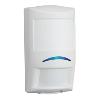
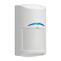
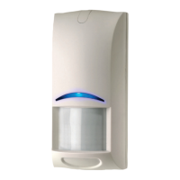
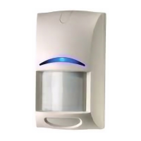
Details P/N, dimensions, and environmental conditions for the dual detector.

Certifications and Compliance

Lists relevant certifications including CEO, RoHS, EN standards, Telefication, UL, C-UL, IMQ, NF A2P, INCERT, FCC/IC.

Configuration and Terminals

DIP Switch Settings

Explains how DIP switch settings and control panel voltage affect detector functions.

Spare Terminals Overview

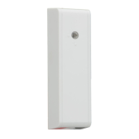
Provides a description of the available spare terminals on the device.

Functional Features

Alarm Memory Function

Explains the Alarm Memory feature, its operation, and LED indicators.

Detector Operation Modes

Walk Test and Alarm Memory Terms

Lists translations for Walk Test and Alarm Memory functions and their polarity settings.

Coverage Patterns

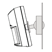
Describes short and long-range detection patterns for Microwave and PIR technologies.

Detector Capabilities

Antimask Feature

Details the activation and deactivation of the detector's antimask feature.

Masking Options

Covers optional masking and optional look-down zones for enhanced detection.

Status Indicators

LED Indicator Meanings

Explains the meaning of various LED states: No activity, Warming up, Dual alarm, Microwave, PIR detection.

Operation and Maintenance

Microwave Range Adjustment

Provides instructions on how to adjust the microwave range for optimal coverage.

Self-Test Procedures

Explains self-test functionality, common failures, and corresponding LED patterns.

Advanced Operational Controls

Remote Self-Test

Details the automatic activation of remote self-test and its expected alarm response.

Key Function Controls

Describes settings for Walk Test LED, Alarm Memory polarity, range selection, and antimask.

Error Reporting and Conditions

Trouble Memory Recall

Explains how to access and clear recorded trouble events from the detector's memory.

LEDs for Specific Faults

Details LED indications for specific conditions like Antimask, Self-test, and Low input power.

System Supervision and Settings

Parameter Settings and LED Functions

Comprehensive multilingual guide to detector settings and their associated LED functions.

Low Power Supervision Activation

Explains the voltage condition that activates the low power supervision feature.

Related product manuals