16 | Application Considerations LM CS Series Heat Pump
LM CS Series Heat Pump8 733 920 847 (2014/01) Subject to change without prior notice
It is imperative that all air be eliminated from the
closed loop side of the heat exchanger to insure
against fouling. In the heating mode, heat is
absorbed from the water loop. A boiler can be
utilized to maintain the loop at the desired
temperature.
Do not overtighten the connections. Flexible hoses
should be used between the unit and the rigid
system to avoid possible vibration. Ball valves
should be installed in the supply and return lines
for unit isolation and unit water flow balancing.
Pressure/temperature ports are recommended in
both supply and return lines for system flow
balancing. Water flow can be accurately set by
measuring the water-to-refrigerant heat
exchangers water side pressure drop.
No unit should be connected to the supply or
return piping until the water system has been
completely cleaned and flushed to remove any dirt,
piping chips or other foreign material. Supply and
return hoses should be connected together during
this process to ensure the entire system is
properly flushed.
After the cleaning and flushing has taken place the
unit may be connected to the water loop and
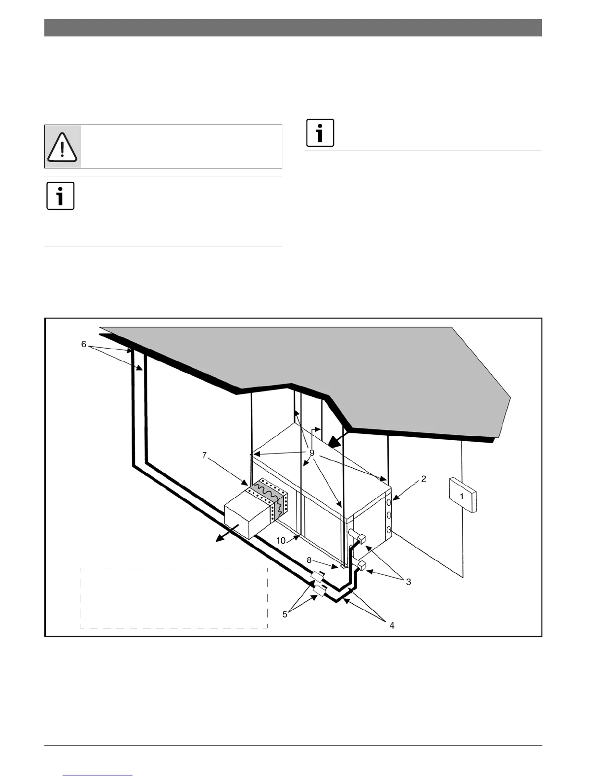
should have all valves wide open. (Figure #14)
Figure # 14
[1] Line voltage disconnect (unit)
[2] Low voltage control connection
[3] P/T ports (optional)
[4] Hose kits (optional)
[5] Ball valves
[6] Supply and return line of central system
[7] Flex duct connection
[8] Hanging bracket assembly
[9] Threaded rod
[10] Hanging bracket assembly
Water piping exposed to extreme low
ambient temperatures is subject to
freezing.
Consult the specification sheets for piping
sizes. Teflon tape sealer should be used
when connecting to the unit to insure
against leaks and possible heat exchanger
fouling.
See specification sheets for water flow vs.
pressure drop information.
Note: Diagram shows typical
installation and is for illustration
purposes only. Ensure access to Heat
Pump is not restricted.

 Loading...