32 en | Typical System Configurations MIC IP starlight 7000i
2017.09 | 0.12 | F.01U.xxx.xxx Installation Manual Bosch Security Systems
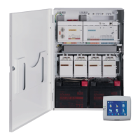
9.3 Typical IP Configuration with VJC-7000-90
Figure9.3: Basic configuration with VIDEOJET connect 7000
1 Ethernet (network) cable (Cat5e/Cat6e) (user-supplied) between a Bosch camera and
the port labeled PoE on VIDEOJET connect 7000
2 Data-only IP cable (Cat5e/Cat6e) to the head-end network
Note: The cable to the head-end also can be fiber optic cable from one of the two SFP
slots.
3 Alarm input / output interface cables (user-supplied)
4 Alarm output cables (user-supplied)
5 120 / 230 VAC, 50/60 Hz
6 Audio input interface cable (user-supplied)
7 External washer pump (user-supplied)
8 Washer output, 2-conductor (user-supplied)
Note: The total length of Cat5e/Cat6e cable must be less than 100 m (328 ft) between the
camera and the head-end system.
 Loading...