Do you have a question about the Bosch MAP 5000 Series and is the answer not in the manual?
Manual describes installation, wiring, initial set-up and maintenance of the MAP 5000 system.
System compliance with certifications and approvals for various regions and standards.
Instructions for safe battery handling, including short-circuit prevention and terminal cover usage.
Guidelines for system installation, including wiring codes, authorized personnel, and material.
Details on planning the system, including enclosure kits and component compatibility.
Considerations for planning system power supply, including inrush current and current limitations.
Wiring possibilities when using a CAN splitter module to divide the external BDB.
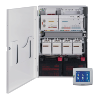
Overview of the system installation within the ICP-MAP0111 control panel enclosure.
Step-by-step guide to removing knockouts from the enclosure door and body.
Instructions for mounting the tamper switch rail inside the enclosure.
Guidance on securely mounting the enclosure to a surface, including space requirements.
Procedure for verifying the AC connection and ensuring safe operation before proceeding.
Steps for installing the power supply unit and its associated accessories.
Procedure for installing the thermistor cable to adjust battery charge voltage based on temperature.
Instructions for mounting the TAE Box to the enclosure back wall.
Steps for mounting the 12 V converter onto the accessory mounting plate.
Procedure for mounting the fuse plate (SIV) and connecting its field wiring.
Guide to mounting the AT 2000 communicator on the accessory mounting plate.
Instructions for installing the ICP-MAP0025 hinged mounting plate inside the enclosure.
Describes mounting of various MAP main panels and Ethernet cable installation.
Steps for mounting the ICP-COM-IF relay module on the hinged mounting plate or mounting rails.
Guide to installing and connecting the wireless modem for GSM/GPRS data transmission.
Details on magnetic antenna mast and rod antenna specifications and usage.
Guide to connecting system modules via the data bus, including color-coded terminal blocks.
Explanation of internal and external data buses and requirements for data bus wiring.
Guidance on mounting the external data bus and bus topology specifications.
How to split the external data bus into independent stubs using a CAN splitter module.
Information on connecting control centers and VdS programming instructions.
Describes the connection of various MAP main panels and their connection strip details.
Procedure for connecting the power supply to the main panel, including AC terminal block and connector cable.
Instructions for connecting LSN gateway components, including shielded wiring requirements.
Details on optional power supply connections and supervision outputs.
Steps for installing and connecting the ICP-MAP0050 and ICP-MAP0055 tamper switches.
Procedure for installing the enclosure lockset, including removing knockouts and securing.
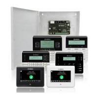
Guidance on mounting location and physical installation of the control center.
Steps for making final power connections, including AC breaker and battery leads.
Information on the Ethernet interface for connecting to a management system.
Checks to perform before initial setup, including cable connections and power supply status.
Guide to performing system programming using the RPS for MAP software.
Instructions and explanations for programming are provided online and via help texts.
Steps to perform standard-compliant programming using RPS for MAP software.
Ensuring fault-free operation by complying with system module and software specifications.
Procedure to check compatibility of software versions for all system modules and the programming software.
Final steps for installation, including applying type labels and locking the enclosure door.
Overview of standard point types and their pre-set properties for system configuration.
Details on programmable output signals and their behavior item types.
Details on functions that can be programmed at outputs, indicated by 'p'.
Explains variants for siren and communicator operation according to EN50131 grade 3.
Details on the ICP-MAP0115 power enclosure and its connections.
Instructions for installing rack mount brackets to the ICP-MAP0120 expansion enclosure.
Information on maintenance intervals, personnel, and applicable regulations.
How to use the installer button for switching installer mode on/off and system restart.
Procedure to restore the panel to its initial state via Failsafe mode and firmware update.
Details on VdS class C requirements and default setting selection.
Procedure to select VdS class C as the default property values setting for compliance.
Notes on connecting the DR2020T printer for service purposes only.
Explanation of the four standard access levels (AE) and how to select them.
Requirements for EN 50131 grade 3 compliance and connecting peripherals.
Procedure to select EN50131 grade 3 as default property values for compliance.
Information on peripherals that must be certified for EN 50131 grade 3 or 4.
Steps for arming/disarming the system without entry or exit delays.
Procedure for arming/disarming with entry and exit delays, including route programming.
Configuration for automatically bypassing points during arming to prevent issues.
Steps for setting up automatic arming and disarming based on time schedules.
Configuration for alarm, trouble, and event outputs via siren and communicator.
Reference to IP Interface section for connecting to a management system.
Notes on connecting the DR2020T printer for service purposes only.
Explanation of the four standard access levels (AE) for system access control.
Requirements for SES compliance, based on EN 50131 grade 3.
Procedure to select EN50131 grade 3 as default property values for SES compliance.
Guidelines for automatic arming/disarming with and without warning signals.
How blocking time can influence area disarming and user permission settings.
Explanation of access levels AE 1, AE 2A, AE 2B, AE 3, and AE 4 for system access.
Details on tamper switch installation and location supervision requirements for the panel.
Functionality for alarm transmission systems according to EN50136-2 SP4 or DP3.
Information on configuring and managing the panel's history log entries.
| Brand | Bosch |
|---|---|
| Model | MAP 5000 Series |
| Category | Security System |
| Language | English |