MAP 5000 Installation | en 15
Bosch Security Systems B.V. Installation manual 2019-09 | 25 | F.01U.168.332
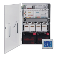
2 Installation
– Use proper anchor and screw sets when installing the enclosure on surfaces. Refer to the
drill template for detailed instructions.
– Ensure that there is enough free space to the left of the enclosure so that the enclosure
door and the ICP-MAP0025 hinged mounting plate have full range of motion. 460 mm (18
in) for a fully opened door or 32 mm (1.25 in) for 90° opened door is required.
– Ensure that there is at least 100 mm (4 in) of space around the enclosure to allow easy
access to cable conduits.
– Leave adequate space below or next to the enclosure for an ICP-MAP0120 expansion
enclosure for future additions to the system.
– To minimize battery depletion, install the enclosure in locations at normal room
temperature.
– Use the ICP-MAP0111 installation mounting template (F.01U.076.204) or the ICP-
MAP0120 installation mounting template (F.01U.076.205)
2.1 Removing the enclosure knockouts
1. Unhinge and remove the enclosure door and set it aside.
2. Remove the enclosure knockouts in the order shown in the figure below.
Enclosure knockouts
Element Description
1 Knockout for wall tamper (required in accordance with EN50131 grade 3)
2 Knockout for TAE box
3 Knockouts for wiring